To me, it looks like he has a dip in supply due to heavy load switching-on. How can the MOV help him with this issue?!
Gajanan Phadte
Gajanan Phadte
Do you want to share AC ground to digital input ground?
No, it's on the spdif side: I' m quoting Russ here: "One thing I have seen people do is connect the - input and GND together for consumer SPDIF on the receiver side. You might want to give that a try as well." Read the link i have provided you , it's interesting. Of course what others have posted are also valid suggestions, but start small, first things first, and work from there...
Good luck
Lock LED flashes very low & no sound😡
Now only I need to fix the BIII dropouts😕
¿can you verified the earth point, is OK?.
If only this switch make the spikes:
you need a varistor in paralel with the switch of start burner in heater, or a varistor in the mains AC of heater.
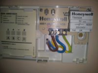
With a varistor in the mains AC of heater still unlocks but I VERIFIED THE EARTH POINT IN THE TEMPERATURE CONTROL AND THE EARTH WAS NOT CONNECTED CONNECTED AND FIXED THE ISSUE🙂
Attachments
....
With a varistor in the mains AC of heater still unlocks but I VERIFIED THE EARTH POINT IN THE TEMPERATURE CONTROL AND THE EARTH WAS NOT CONNECTED CONNECTED AND FIXED THE ISSUE🙂
Congratulations!!!! Its generally best to eliminate problems at the source, as you have shown. My wife says that all too often, when she looks at me....

Thanks.
I want to try the a loop breaker as described in the Elliot Sounds Audio pages but I have a doubt, how have I to wire the zero volt line: at the digital input RCA ground or at the analog output RCA?
Felipe
Attachments
I read where to connect the zero volt line: "This is most commonly taken directly from the centre tap of the main amplifier filter capacitors, but should always be connected to a point where there is high current wiring back to the transformer"
Now the questions are:
-DAC box have 3 PSU: 1 positive digital + 2 analog (1 positive & 1 negative) where to connect or have I to connect in each mains filter cap?
-I'm using balanced & unbalanced outputs, have I to connect the zero volt line in each output ground?
-Have I to connect the zero volt line in each input ground?
Thanks for help.
Felipe
- Status
- Not open for further replies.
- Home
- Amplifiers
- Power Supplies
- how to eliminates AC spikes