nigelwright7557 said:I stripped numerous bought in mains filters and they were all around 2u2.
Perhaps they were 2n2?
2n2 = 2.2nF
2u2 = 2.2uF = 2200nF
Hi,
I agreed with the suggested uses of MOV in thread 4. But I would install it at the source that is at the AC air conditioning. This will prevent the spread of the noises through the house. I will use an MOV of 270 volts. Some time people use too high voltage to operate and would not do anything.
I agreed with the suggested uses of MOV in thread 4. But I would install it at the source that is at the AC air conditioning. This will prevent the spread of the noises through the house. I will use an MOV of 270 volts. Some time people use too high voltage to operate and would not do anything.
Are you sure? 2u2 at 50Hz 240V will inject 166mA into the earth conductor. Plenty enough to trip a 30mA ELCB, and possibly enough to kill someone if the earth conductor breaks. 1mA wll make you jump.
PS I am tempted to ask the mods to remove your mains filter circuit from post 13 on the grounds of safety, but I will give you the chance to justify it first.
I am pretty sure it was 2u2 but it was for a 30amp mains system not an amplifier.
I could have read them wrong as 2n2 ?
It was a 10 years ago when I did the work so I could be mistaken.
Last edited:
Industrial practice may be different, but 2u2 still sounds wrong. I have reported your post 13 to the mods on the grounds of safety. Nothing personal, but we don't want to fry a newbie!
Industrial practice may be different, but 2u2 still sounds wrong. I have reported your post 13 to the mods on the grounds of safety. Nothing personal, but we don't want to fry a newbie!
Apologies to the OP but I read the wrong values from my records, the earth capactors should be 4n7 Y1 or Y2.
I will change the schematic so it reads correctly ASAP.
I use in mine power line AC filter & surge suppresor:
MOV
V275LA40AP - LITTELFUSE - VARISTOR, 140J, 275VCA | Farnell España
All caps are Class X1
It's correct?
Can MOVs be damaged? Have I to change for a news ones?
MOV
V275LA40AP - LITTELFUSE - VARISTOR, 140J, 275VCA | Farnell España
All caps are Class X1
It's correct?
Can MOVs be damaged? Have I to change for a news ones?
Can MOVs be damaged?
Yes, they can. In bad cases, they split open.
I witnessed a MOV died once. Internally, it blinked 3-4 times, like a red/orange led. Didn't split open though.
Merlin,
The most effective place to attennuate spikes is at the source. Your heating system is the source and you should see if you can take appropriate steps at the source. If it is your own heating system, investigate whether you can add a snubber -
http://www.kemet.com/kemet/web/homepage/kechome.nsf/file/General%20Information%20-%20RC%20Units/$file/F9000_GenInfo_RCUnits.pdf
or check if the heating system has built in supression that has failed.
If it is a common heating system shared among many, good luck....
The Jon Risch filter is a reasonably good filter. But as others have said, the line-ground & neutral-ground capacitors must be minimally Y2 rated, an 'X' rating is not appropriate, but many X1 capacitors are also rated Y2. The 0.1uf for C1,C2 are quite high for a 'to ground' Y cap, Nigel's 4700pf(4.7nf) value is more appropriate.
The nominal 275 vac rating of the referenced varistor is fine, but if I could address that known spike at the source end, I'd use a 300vac rated version to minimize the 'wear out' of the varistor.
If the spike is caused by contact closure on your heating system, that spike is single ended (differential), rather that common mode, and the minimal leakage inductance of that JWM 8108 1mh CMC, 4.5uH, is unlikely to help
Nigel,
Is your filter circuit intended for source components only? The 1mH differential inductors (do you mean both to be single 1mH CMC?) shown in your schematic are going to constrain the current draw of the typical solid state power amplifier.
FWIW,
Paul
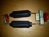
 Nigel, your corrected schematic still showed 2.2uF to earth. Please post the correct values. I will update your posts. Thanks.
Two pics of an identical Jon Risch power conditioner that I have as spare.
I have my own heating system isn't shared, yes I know that the most effective to attenuate spikes is in the source that's the reason I asked to put a cap in the inlet heating system, could you post a snubber schematic?
I have my own heating system isn't shared, yes I know that the most effective to attenuate spikes is in the source that's the reason I asked to put a cap in the inlet heating system, could you post a snubber schematic?
Attachments

The most effective place to attennuate spikes is at the source.
Good advice. And when using snubbers either across the line or a contact, it's best to avoid a straight capacitor, and use an RC snubber. Some suggest the load resistance to be sufficient as series R, but every time I've checked for optimal values with a scope, it never is.
http://www.paktron.com/pdf/Quencharc_QRL.pdf
You need to reload your page, the old picture is stuck in your cache.
I have renamed it so that doesnt happen again.
An externally hosted image should be here but it was not working when we last tested it.
Last edited:
Merlin,
Nigel,
Is your filter circuit intended for source components only? The 1mH differential inductors (do you mean both to be single 1mH CMC?) shown in your schematic are going to constrain the current draw of the typical solid state power amplifier.
FWIW,
Paul
It was used on a fusion plactic pipe welding systenm that took 30 amps and didnt cause any problems. It wasnt common mode. While it filters it was also designed to reduce EMI.
some what off topic.
Fix the source of the problem
Have your heater/ a/c system checked for weak motor start/run capacitors.
Fix the source of the problem
Have your heater/ a/c system checked for weak motor start/run capacitors.
It was used on a fusion plactic pipe welding systenm that took 30 amps and didnt cause any problems. It wasnt common mode. While it filters it was also designed to reduce EMI.
For source components, I do try and get about 1 mH of differential inductance, along with 20+ mH of common mode inductance with appropriate X & Y caps. But for linear, cap input power supply fed solid state amps, differential inductance above 25uH has been problematic. YMMV
Have you actually used this filter in an audio system?
Have you actually used this filter in an audio system?
No I have not. I just input it as a starting point.
Merlin,
I tried to provide a link to a technical pdf at the Kemet/Rifa site, unsuccessfully.
You can get it here -
FEBG - RC Snubber Capacitors
and click on the link 'Technical info specific to RC snubber networks'
in the upper left. But the information is much the same as Zigzagflux's url -
http://www.paktron.com/pdf/Quencharc_QRL.pdf
zigzagflux would offer you better advice on the appropriate values for a series connected resistor- capacitor, that comprises a snubber, than I could.
Hopefully, Mike567's suspicion of a faulty motor run and/or start capacitor will prove true, and be easily replaced, solving your problem. Otherwise, it may well be relay/switch contact switching noise requiring appropriate snubbing. Occasionally, furnace/boiler manufacturers have available noise snubbing kits.
Regards,
Paul
- Status
- Not open for further replies.
- Home
- Amplifiers
- Power Supplies
- how to eliminates AC spikes