I'm not sure how accurate a DMM is above ~400Hz, maybe use a loopback signal from the audio interface at ~100Hz and measure it with the DMM and use that as the cal? For 1kHz I think a o-scope with a RMS measurement would be better?
Yes, if all you plan to measure are voltages going to the input jack of the 2i2. You should do this as minimum case to convince yourself how REW works.
But in practice, when measuring a power amp putting out say 28.3Vrms into a dummy resistor load (8ohm non inductive 100w heatsinked type), connect the attenuator (on -26dB setting) and feed that to REW. Apply 28.3Vrms to the dummy load measure with DMM across the load. What you want to do is adjust gain knob on 2i2 until it lights green and adjust to get about -10dB full scale of the 2i2. This way, you are using its max (intrinsic) dynamic range and leave 10dB away from clipping. Now click calibrate and enter the measured Vrms from DMM. Now, the 0dB FS on the graph corresponds to whatever max you sent at, in this case. 28.3Vrms.
Note that you cannot touch any gain knobs from here other measurements if you want that scale to be consistent.

But in practice, when measuring a power amp putting out say 28.3Vrms into a dummy resistor load (8ohm non inductive 100w heatsinked type), connect the attenuator (on -26dB setting) and feed that to REW. Apply 28.3Vrms to the dummy load measure with DMM across the load. What you want to do is adjust gain knob on 2i2 until it lights green and adjust to get about -10dB full scale of the 2i2.
I feel so dense right now.
Why should I use the voltage at the dummy load when the interface only sees the voltage at the output of the attenuator?
I am sorry, I am struggling.
Because you are testing what is applied to the dummy load - it’s not important what the actual voltage that’s measured at the 2i2 (except that it’s not clipping and has good dynamic range).
For example, the test condition is power in watts applied to the 8ohm load, not the voltage at the input to the ADC input.
You could do it that way and then measure the exact attenuation and post process apply it. But better to know without.
For example, the test condition is power in watts applied to the 8ohm load, not the voltage at the input to the ADC input.
You could do it that way and then measure the exact attenuation and post process apply it. But better to know without.
Because you are testing what is applied to the dummy load - it’s not important what the actual voltage that’s measured at the 2i2 (except that it’s not clipping and has good dynamic range).
For example, the test condition is power in watts applied to the 8ohm load, not the voltage at the input to the ADC input.
You could do it that way and then measure the exact attenuation and post process apply it. But better to know without.
This morning, this seems to make a lot more sense to me. I don't know what my brain did overnight, but it worked.
Your patience and explanations were instrumental no doubt.
I did a whole bunch of measurements and I think I am getting reasonable results.
Also the magic box, headphones version is done:
If you do not find a 9K0 or 90k resistor in your stash - just build the 3 resistor divider, for instance
a 10k series resistor,
parallel with 100k resistor gives 9k09
and with 1k0 parallel resistor
the unloaded attenuation is 20.08dB.
A simple approach that obviously works with any other value...
For higher precision you might add 1MOhm, 10MOhm... - do the math😉
a 10k series resistor,
parallel with 100k resistor gives 9k09
and with 1k0 parallel resistor
the unloaded attenuation is 20.08dB.
A simple approach that obviously works with any other value...
For higher precision you might add 1MOhm, 10MOhm... - do the math😉
18K // 18K = 9K
The tolerances of the resistors may add up. You can trim with a DC voltage source and a DMM; most of these latter have better than 1% resolution.
The tolerances of the resistors may add up. You can trim with a DC voltage source and a DMM; most of these latter have better than 1% resolution.
I don’t worry about the exact attenuation as I measure the voltage at the DUT directly with an Oscope and a Fluke DMM. My main reason is to avoid blowing the input opamps on the USB audio interface.
I am not entirely sure if this thread is only about measuring distortion for amplifier and electronics, or loudspeakers as well?
Anyway, I think you guys can still help me out here.
So since measuring distortion in ARTA is not the greatest, I am gonna move a part of my workflow to REW.
Mostly because the distortion graph is easier to customize + it give me the opportunity to directly export the IR.
Unfortunately when I am trying to calibrate the sound pressure levels with my B&K calibrator, the levels don't line up between REW and ARTA.
This is even double checked with a calibrated sound level meter, which matches up with ARTA.
The procedure in ARTA is super straightforward;
Setup -> calibrate device -> Estimate Mic sensitivity -> turn on calibrator -> put mic in calibrator, e voila
As far as I understand, in REW we have to go to the SPL meter and hit calibrate.
While the SPL meter seems to read the correct value (94dB), when I am doing a regular measurements, the results are off by about 9dB or so. (I have to check that again)
Output is set to 0dBFS.
Sweep level in settings is also set to 0dBFS.
I can set this value correctly when I fiddle around with the "call data" that is kinda hidden in the "input selection dialogue".
But that is very far from being convenient.
Second question,
Is there a option to add smoothing to distortion graphs?
Because when I hit graph -> smoothing, nothing happens.
Hello,
I wanted to ask you for advice.
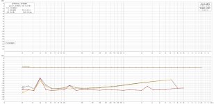
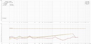
I built a measuring bench with REW, a Scarlett 2i2 and a load of 8R 100W in a box to measure amp boards.
The problem is that depending on the type of attenuator, I don't get the same result at all (see the two measurements).
I made two -20dB attenuators to compare them. One with 1K/110R and another with 10K/1K1. The REW and Scarlett settings are the same.
So, I don't know where the truth is.
Regards,
Stef.
The name of the files describe the mesure.
I wanted to ask you for advice.
I built a measuring bench with REW, a Scarlett 2i2 and a load of 8R 100W in a box to measure amp boards.
The problem is that depending on the type of attenuator, I don't get the same result at all (see the two measurements).
I made two -20dB attenuators to compare them. One with 1K/110R and another with 10K/1K1. The REW and Scarlett settings are the same.
So, I don't know where the truth is.
Regards,
Stef.
The name of the files describe the mesure.
Attachments
A more accurate attenuation is 900/100r and 9000/1k.
Also the input impedance of the Scarlett will affec the results, especially with the 10k/1k1 attenuator.
Also the input impedance of the Scarlett will affec the results, especially with the 10k/1k1 attenuator.
Hi!
For the stepped sin, I use the internal REW oscillator after calibration of the devices.
For the spectrum, I use a Victor's Oscillator in a box (with an attenuator -20dB inside, I forgot the R values). With the internal REW oscillator, the mesure is bad.
The Scarlett input impedance is 60K.
Stef.
For the stepped sin, I use the internal REW oscillator after calibration of the devices.
For the spectrum, I use a Victor's Oscillator in a box (with an attenuator -20dB inside, I forgot the R values). With the internal REW oscillator, the mesure is bad.
The Scarlett input impedance is 60K.
Stef.
Last edited:
Ahh, misunderstanding . . . . I am not asking about how you generate a sin wave . . .
I am asking the input devices of the amplifier you are measuring - Are they BJT or some kind of FET ?
I am asking the input devices of the amplifier you are measuring - Are they BJT or some kind of FET ?
You didn't mention if you're using the 2i2's mic input (3 KOhm impedance) or the line (i.e. TRS) input (60 KOhm impedance). It would also help us diagnose if you posted your stepped sine settings.
- Home
- Design & Build
- Software Tools
- How to - Distortion Measurements with REW