I do not know the details of your ACA amp. My experience with TPAxxxx from TI is that the symmetric full bridge configuration is one order of magnitude better than the asymmetric half bridge. To verify this the connecting cable incl attenuator must be fully symmetrical.
D'oh! Yeah the ACA mini is using the SMPS from the diyaudio store. That makes sense.
Bucks-
I will look into full bridge vs asymmetric half - and the connecting cables as well. More to think about. Thanks again.
Bucks-
I will look into full bridge vs asymmetric half - and the connecting cables as well. More to think about. Thanks again.
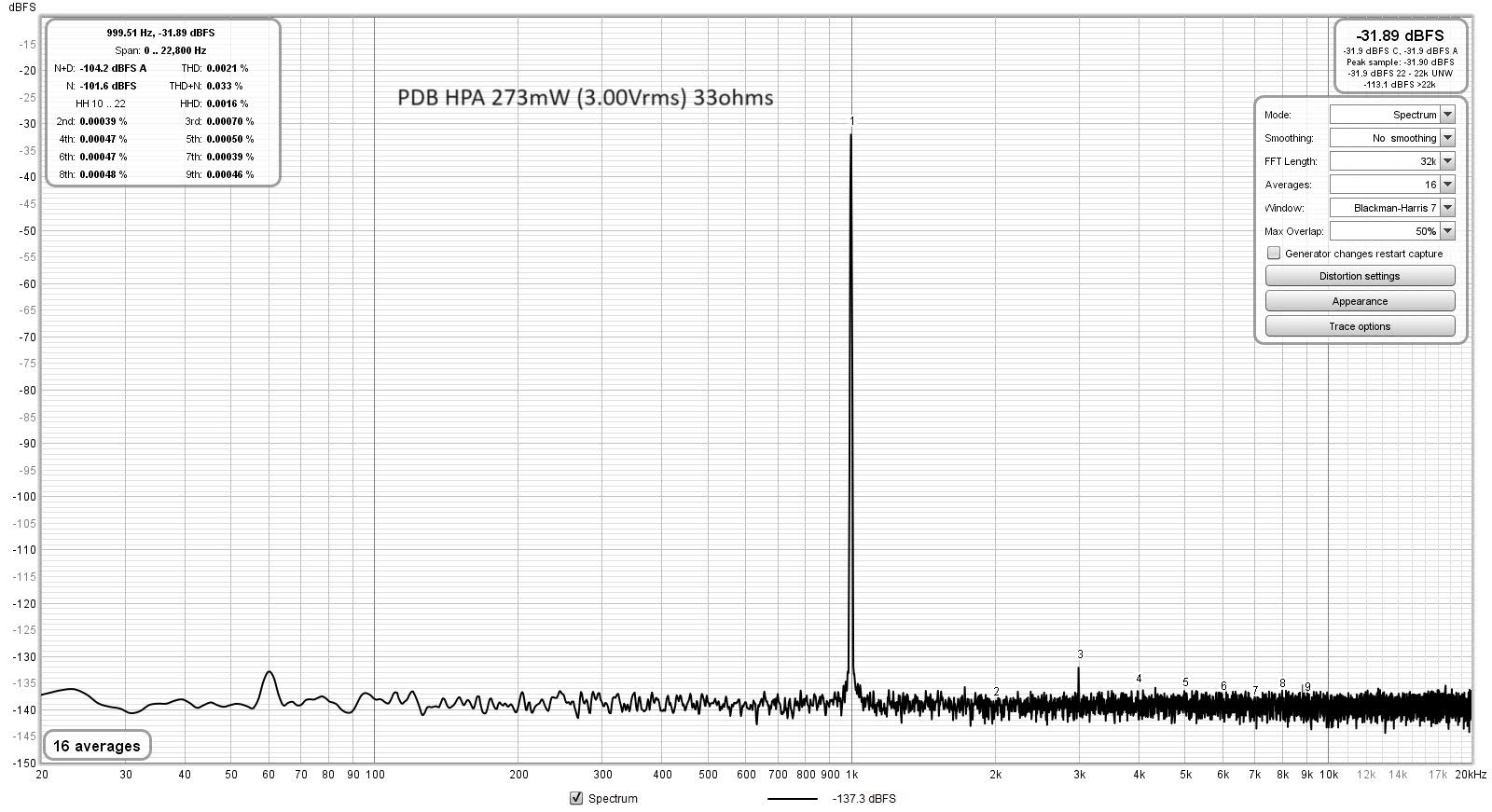
The ACA is a nice amp for listening as it has a nice SE Class A harmonic profile (dominant 2nd and third and monotonically descending higher orders). But it is not going to win any THD shootout - it is in fact, the worst measuring amp in ASR's histogram like view of THD/Sinad amp measurements. However, that doesn't say anything about how good it sounds. If you want to test your measurement setup with a bit more of a performance amp, try a typical chip amp or other SS amp. A Class D amp will require a proper high freq carrier filter (see earlier posted examples in this thread using 4 stage CLC filters) to get good measurements without aliasing your data. Headphone amps are also useful for testing out measurement setups. I recently measured this on a small diamond buffer putting 273mW into 33ohms. This is amp running on batteries and using Victor's 1kHz osc as the source.
It lets you use smaller resistor dummy loads (1W 33R metal thin film resistor), but you still need an attenuator. I have learned the hard way to always use an attenuator on any amp measurement as I have damaged the front end opamp on my Focusrite's before. At 3.0Vrms, the signal could have gone into the Focusrite 4i4 front end without an attenuator, but then I would have risked damaging it if there was a pop or something from the amp.
I personally like to display in dBFS and show the THD window in same plot, and always specify what your conditions are (load and excitation in Vrms or Vpp). I like to use a high quality TrueRMS type DMM (like a Fluke 105 or 106) to do the Vrms measurements in parallel right at the load dummy resistor. An oscope simultaneously attached will give you good info on if signal is clipping or if perhaps you are suffering an oscillatuon (out of band) which won't show up as THD but might show up as a noise floor or excess hash.
There is a good video here showing the perils of posting measurements without details of how the analyzer was setup. You can get wildly different measurements with same setup but tweaks of the settings in an Audio Precision that is so popular.
Similalrly, with REW, there are settings to be sure - and another reason why it is good to show the settings dialog exploded.
Last edited:

I personally like to display in dBFS and show the THD window in same plot, and always specify what your conditions are (load and excitation in Vrms or Vpp).
Agree totally as results are meaningless without knowing the conditions.
A small point here, the optimum overlap for the 7-term Blackman-Harris window is 85.7%, as outlined here:Similalrly, with REW, there are settings to be sure - and another reason why it is good to show the settings dialog exploded.
https://ccrma.stanford.edu/~jos/sasp/COLA_Examples.html
The 87.5% setting in RTA is close enough.
Thanks for that tip on BH and filter overlap. Reading that link and other discussions in web seem to indicate 2/3 overlap or 67% - where do you see 87.5%?
On the link, it's on the line:
More on optimum overlap here (page 17):
https://pure.mpg.de/rest/items/item_152164_2/component/file_152163/content
However, they only have a third-order Blackman-Harris window in their collection (BH2), with an overlap of 66.1%, which is close to 2/3.
- Any member of the L -term Blackman-Harris family with...
More on optimum overlap here (page 17):
https://pure.mpg.de/rest/items/item_152164_2/component/file_152163/content
However, they only have a third-order Blackman-Harris window in their collection (BH2), with an overlap of 66.1%, which is close to 2/3.
Ok - I see denominator is 7 (from Blackman Harris 7). But where does the M=6 come from? Excuse my ignorance.
M is window size and why is it 6?
I was reading this but still don’t see where M=6 comes from.
https://www.dsprelated.com/freebooks/sasp/Blackman_Harris_Window_Family.html
I think in REW, the M and L are all handled by the selection of the Window function in the drop down.
The % overlap is a separate sliding window filter?
Maybe John M. can answer what is happening here and the effect of the % overlap selection.
M is window size and why is it 6?


I was reading this but still don’t see where M=6 comes from.
https://www.dsprelated.com/freebooks/sasp/Blackman_Harris_Window_Family.html
I think in REW, the M and L are all handled by the selection of the Window function in the drop down.
The % overlap is a separate sliding window filter?
Maybe John M. can answer what is happening here and the effect of the % overlap selection.
Last edited:
Merry Christmas!
M and L are indeed set by the user in REW, but they do not automatically define the overlap size.
Referring to the formula for R = M/L, R stands for the "hop size", i.e. the number of samples from the current data record to be discarded when composing the next one to be processed by the DFT, M is the window length, which is equal to the DFT length (in your case 32k), and L is the number of coefficients in the window formula.
Now inserting the numbers, we get R=32768/7, but the essential result is that 1/7 of the current data record, or its 14.28%, is discarded. The remaining 6/7, or 85.7%, will be reused, and thus represent the overlap.
Going a bit deeper, the overlap size is not only a function of the window "order" L, but also depends upon the time-domain characteristics of the signal to be processed. For example, Trethewey (2000):
https://sci-hub.st/10.1006/mssp.1999.1274
finds the optimum overlap of 62.5% for the Hann window in the case of his signal, whereby the standard overlap size for the Hann window is 50%.
Fortunately, when performing spectral analysis of stationary signals in the audio domain the overlap size is not a major issue.
There's a good deal of info on many windows including overlap ratios here: https://holometer.fnal.gov/GH_FFT.pdf
This is an amazing thread, but I am still uncertain about the proper wiring for the 2i2.
The line outputs on the 2i2 are L/R 6.35mm can TRS or TS sockets.
If the DUT amp takes L/R RCA inputs, I assume 2 6.35mm TS to RCA cables are needed.
Now, the 2i2 L/R inputs can be 3-pin XLR jacks, or 6.35mm TRS jacks, or 6.35mm TS jacks.
XLR inputs are for microphones only, the doc says.
Then, if the DUT amp has differential outputs, I assume cables ending in 6.35mm TRS jacks would be needed to go from amp outputs to 2i2 inputs.
If the DUT amp has single-ended outputs, then I assume cables ending in 6.5mm TS jacks would be needed to go from amp outputs to 2i2 inputs.
Excluding attenuator and dummy load from the discussion for now. I know they are needed.
Did I get all this right?
Use TS to RCA adapter plugs on the audio out. For audio input, get a cheap XLR cable and cut it to expose the wires and you now have a shielded test cable to connect to the dummy load. Use the +ve and -ve across the dummy load resistor (with attenuator). The GND can be used to connect to chassis of amp. So even for single ended output amps, use differential to measure voltage across dummy load. It helps to reduce common mode noise (EMI and other sources of hum).
get a cheap XLR
So, we do want the built-in microphone preamp to be in-circuit?
And we will use the attenuator to make sure we don’t make it clip or kill it?
Use TS to RCA adapter
OK
I imagine a box, to measure headphone amplifiers. 1 channel only.
It would contain 2 dummy loads (30R and 300R) and 2 Akitika-style attenuators.
In the back, on the left and the right, there would be a 6.35mm socket and a 4-pin XLR socket.
In the front, on the left and the right, there would be a 3-pin XLR socket and a rotary switch.
The enclosure would shield the whole thing.
Is this a bad idea?
Before making the enclosure just P2P wire it or use alligator clips etc to see if it works. There is no need for a box to shield things. It’s high level high current audio signals. Always test as “plank” experiment in the open before investing time and money making a nice box.
In often use the RTA mode to identify speaker cabinet resonances or driver frame resonances so that I can go on and fix it with damping materials or braces. It also shows drivers with inherent cone breakup mode issues.
- Home
- Design & Build
- Software Tools
- How to - Distortion Measurements with REW