You find a detailed test here: https://www.audiosciencereview.com/...rlett-2i2-audio-interface-gen-3-review.10187/
The Sinad of the Scarlett is about 101dB, not bad at all.
The Sinad of the Scarlett is about 101dB, not bad at all.
What's the lowdown on how to build this? Split signal with resistors to 2 XLRs? Or no resistors, just direct split?RCA to xlr cable, no mono mode
Hi all here 🙂
I was in luck to get my hands on my grownup son's RIAA for a few day's.
Thought it could be fun to test it, so digging down the rappithole to figure out howto do that I did.
I found the "reverse" RIAA calibration file on another forum.
It was a good learning experience 👍
The data::


I was in luck to get my hands on my grownup son's RIAA for a few day's.
Thought it could be fun to test it, so digging down the rappithole to figure out howto do that I did.
I found the "reverse" RIAA calibration file on another forum.
It was a good learning experience 👍
The data::
- RIAA freq response 20hz-20,000hz +/- 0.5dB, S/N ratio >85dB
- THD <0.05%, input sensitivity 3.0mV
- Nominal / max output 300mV / 1.8V
- Output impedence 200 ohms, input 47kohm /220 pF

Very nice work, @lykkedk , congratulations!
I'm a little surprised that the circuit board of the "TC-750 Professional Moving Magnet Preamp" seems not to contain (a) any internal test points, or (b) any resistor-pairs or capacitor-pairs which allow fine tuning of RIAA component values by series- or parallel-connected components. To get capacitor values within 2% and resistor values within 0.4%
I'm a little surprised that the circuit board of the "TC-750 Professional Moving Magnet Preamp" seems not to contain (a) any internal test points, or (b) any resistor-pairs or capacitor-pairs which allow fine tuning of RIAA component values by series- or parallel-connected components. To get capacitor values within 2% and resistor values within 0.4%
Hi @Mark Johnson
I'm not much into the RIAA stuff, but I see what you mean of course.
It's actually not very expensive, and the sound is good on his minor stereo with an old Thorens i renovated to him year and years back.
I hoped that there was an opamp or two inside to try swapping with newer ones, but only transistors as you can see.
Well thanks for your kind words.
Jesper.
It's a crude 3 transistor design, with mylar caps. That it can do +/- 0.5dB RIAA is sort of miraculous. 🙂...
I'm a little surprised that the circuit board of the "TC-750 Professional Moving Magnet Preamp" seems not to contain (a) any internal test points, or (b) any resistor-pairs or capacitor-pairs which allow fine tuning of RIAA component values by series- or parallel-connected components. To get capacitor values within 2% and resistor values within 0.4%
Note ... below is long, but I've tried to put in relevant information in order to get some much-needed help. My thanks in advance for anyone willing to read and help. 🙂
It's been a while since I had used REW for distortion measurements. I've swapped to a new computer and the latest version of REW. I've also... I hope... learned a bit more since I last used it. I think there were errors in both hard wiring and the software setup when I first started trying to use REW to measure amplifier distortion. I'm going to try and do a series of more 'serious' measurements, so I'd like to improve / refine my setup and technique. I'm still doing this as a hobbyist, but I'd like more accurate / precise / repeatable measurements.
The setup...
I've read through (skimmed really) the thread again along with my old notes. I haven't found many pics or detailed descriptions of how people are connecting from the amp output to their DAC / ADC; which in my case is the Focusrite 4i4 3rd Gen.
1) Hardware and connections / Initial Software Settings -
Focusrite Front Panel - Signal Input From Amp
I went back through the Focusrite manual along with the thread again. I've read that the mic input should be used for lowest noise. Perfect. I got lucky. However, I'm not sure I'm connecting to the mic input in the best way or setting up the software properly.
There are two options for the mic input XLR or 1/4" (TS or TRS). The manual says that the... "preamplifier stages are automatically configured for a microphone when you plug an XLR into an input, and for a line or instrument when you connect a jack plug. Select INST from Focusrite Control (‘INST’ illuminates red) if you are connecting musical instrument, e.g., a guitar in the example, via a TS guitar jack. Deselect INST if you are connecting a line level source such as a keyboard, synthesiser or the balanced output of an external audio mixer via a TRS jack." Previous gen manuals noted a gain change between using XLR and 1/4" jack plugs, but the Gen 3 does not mention this.
The specs for the mic input are below (Bold was added for my own ease of conversions / thoughts)
Using the mic input with an XLR connection, and with 10x voltage divider; I should be able to run up to ~21Vrms out of an amplifier and still be within the threshold for the Focusrite Mic input (with no padding). So, I could conceivably measure amplifier output / distortion at up to 55W (assuming an 8 ohm load). I'll likely never do that, but is that correct? As I write my process, I want to note practical limitations.
tl;dr - Is using the front panel input (1) with an XLR connection the best connection? I've only read one exception due to the input impedance, but I don't think that applies here.
Focusrite - Back Panel - Output Signal to Amp
A few things that I think I've learned...
On the back of the 4i4 there are 4 outputs labeled line out. These seem to possibly be user configurable. However, what I've found after resetting everything to factory defaults is that outputs 1 and 2 seem to be 'variable outputs', and more importantly, their output is adjustable with the monitor 'volume knob' on the right front. Outputs 3 and 4 seem to be 'fixed' outputs; and their output is only controlled by varying the input level. I am not sure if the 'monitor' knob is a resistive potentiometer or some digital control, but I think using the fixed outputs is my best bet. I can vary the level sent to the amplifier using the controls within REW. That seems much more repeatable than using a manual knob. I could likely read more to learn more, but frankly I'm exhausted at this point. I had been using the variable outputs and tweaking the volume / gain to get the appropriate voltage at the output of the amp, but I think this may be a better approach.
tl;dr: Is using the fixed output and controlling the output level through the generator in REW the correct approach?
An observation - I was pulling my hair out trying to get a signal. REW using ASIO drivers and selecting the Focusrite USB ASIO as the device DOES NOT allow the user to choose the output from the back of the Focusrite. I thought it did. That was probably my misinterpretation of something...somewhere and/or user error. When I saw 4 outputs as selectable, I thought that I needed to tell REW that I was using Output 3 on the back of the Focusrite. NO. It seems that REW MUST be set to Output 1 or no signal at all goes through the Focusrite. Again, this could be me screwing something up, but it's the only way I could get it to work. I finally just hooked it up to my PC to see which outputs had signals. Even though I am using Output 3, I have selected Output 1 within REW. It works 🤷♂️

The soundcard calibration seemed very straight forward. Measure (Calibrate soundcard). Save the measurement file. Make cal file.
tl;dr - Do the settings above look correct?
Here shots of the loopbacks under these conditions using the RTA and distortion measurement settings I have read are most appropriate throughout the thread. Note - I read that varying slightly from 1kHz is advisable, but I forgot for this measurement.


tl;dr - Any suggestions?
Output connection of Focusrite to Input of Amp
Hand-made 1/4" TRS Jack Plug to RCA. I can wire a 1/4" TRS to XLR for amps with differential input, but I'm not quite sure if the Focusrite does differential output. For now, this seems to work. Any concerns? Does anyone use differential input on appropriate amps for measurements? If so, how do you connect from the Focusrite (or similar) output to the amp input? A wiring diagram would be greatly appreciated.
Output connection of Amp back to Input of Focusrite
Speaker output to dummy load with 10x voltage divider. DMM set to ACV on dummy load.

Software Settings - Generator / RTA
I think everything displays on screen, so I don't think I need to type out all the settings. If some are missing, please let me know.
Below is a measurement at 2.8V output into 8 ohms on an ACA v1.8.
Channel 1

Channel 2

tl;dr - Anything that should be changed in distortion settings etc.? Any concerns or comments?
If you've made it this far, you have my gratitude.
So... even though I've read the thread... many times... if someone could point me toward the resources (potentially more concise) for how to interpret and visualize the phase of the distortion, I'd be even more grateful. i.e. What phase within REW corresponds to "negative 2nd" vs. "positive 2nd"? I am reasonably certain that I saw someone show the actual sine wave of the fundamental vs. the distortion, but darned if I can find it. Was that in ARTA?


It's been a while since I had used REW for distortion measurements. I've swapped to a new computer and the latest version of REW. I've also... I hope... learned a bit more since I last used it. I think there were errors in both hard wiring and the software setup when I first started trying to use REW to measure amplifier distortion. I'm going to try and do a series of more 'serious' measurements, so I'd like to improve / refine my setup and technique. I'm still doing this as a hobbyist, but I'd like more accurate / precise / repeatable measurements.
The setup...
I've read through (skimmed really) the thread again along with my old notes. I haven't found many pics or detailed descriptions of how people are connecting from the amp output to their DAC / ADC; which in my case is the Focusrite 4i4 3rd Gen.
1) Hardware and connections / Initial Software Settings -
Focusrite Front Panel - Signal Input From Amp
I went back through the Focusrite manual along with the thread again. I've read that the mic input should be used for lowest noise. Perfect. I got lucky. However, I'm not sure I'm connecting to the mic input in the best way or setting up the software properly.
There are two options for the mic input XLR or 1/4" (TS or TRS). The manual says that the... "preamplifier stages are automatically configured for a microphone when you plug an XLR into an input, and for a line or instrument when you connect a jack plug. Select INST from Focusrite Control (‘INST’ illuminates red) if you are connecting musical instrument, e.g., a guitar in the example, via a TS guitar jack. Deselect INST if you are connecting a line level source such as a keyboard, synthesiser or the balanced output of an external audio mixer via a TRS jack." Previous gen manuals noted a gain change between using XLR and 1/4" jack plugs, but the Gen 3 does not mention this.
The specs for the mic input are below (Bold was added for my own ease of conversions / thoughts)
- Frequency response: 20Hz - 20kHz ± 0.1dB
- Dynamic range: 111dB (A-weighted)
- THD+N: <0.0012% (minimum gain, -1 dBFS input with 22 Hz/22 kHz bandpass filter)
- Noise EIN-128dBu (A-weighted)
- Maximum input level: +9 dBu (no PAD) => 2.1Vrms; +16 dBu => 4.9Vrms (PAD selected); measured at minimum gain
- Gain range: 56dB => Maximum 631X
- Input Impedance: 3kΩ
- Frequency Response: 20 Hz to 20 kHz ±0.1 dB
- Dynamic Range: 110 dB (A-weighted)
- THD+N: <0.03% (minimum gain, -1 dBFS input with 22 Hz/22 kHz bandpass filter)
- Maximum Input Level +12.5 dBu => 3.2Vrms (no PAD); +14 dBu => 3.9Vrms (PAD selected); measured at minimum gain
- Gain Range 56 dB => Maximum 631X
- Input impedance 1.5 MΩ
Using the mic input with an XLR connection, and with 10x voltage divider; I should be able to run up to ~21Vrms out of an amplifier and still be within the threshold for the Focusrite Mic input (with no padding). So, I could conceivably measure amplifier output / distortion at up to 55W (assuming an 8 ohm load). I'll likely never do that, but is that correct? As I write my process, I want to note practical limitations.
tl;dr - Is using the front panel input (1) with an XLR connection the best connection? I've only read one exception due to the input impedance, but I don't think that applies here.
Focusrite - Back Panel - Output Signal to Amp
A few things that I think I've learned...
On the back of the 4i4 there are 4 outputs labeled line out. These seem to possibly be user configurable. However, what I've found after resetting everything to factory defaults is that outputs 1 and 2 seem to be 'variable outputs', and more importantly, their output is adjustable with the monitor 'volume knob' on the right front. Outputs 3 and 4 seem to be 'fixed' outputs; and their output is only controlled by varying the input level. I am not sure if the 'monitor' knob is a resistive potentiometer or some digital control, but I think using the fixed outputs is my best bet. I can vary the level sent to the amplifier using the controls within REW. That seems much more repeatable than using a manual knob. I could likely read more to learn more, but frankly I'm exhausted at this point. I had been using the variable outputs and tweaking the volume / gain to get the appropriate voltage at the output of the amp, but I think this may be a better approach.
tl;dr: Is using the fixed output and controlling the output level through the generator in REW the correct approach?
An observation - I was pulling my hair out trying to get a signal. REW using ASIO drivers and selecting the Focusrite USB ASIO as the device DOES NOT allow the user to choose the output from the back of the Focusrite. I thought it did. That was probably my misinterpretation of something...somewhere and/or user error. When I saw 4 outputs as selectable, I thought that I needed to tell REW that I was using Output 3 on the back of the Focusrite. NO. It seems that REW MUST be set to Output 1 or no signal at all goes through the Focusrite. Again, this could be me screwing something up, but it's the only way I could get it to work. I finally just hooked it up to my PC to see which outputs had signals. Even though I am using Output 3, I have selected Output 1 within REW. It works 🤷♂️
The soundcard calibration seemed very straight forward. Measure (Calibrate soundcard). Save the measurement file. Make cal file.
tl;dr - Do the settings above look correct?
Here shots of the loopbacks under these conditions using the RTA and distortion measurement settings I have read are most appropriate throughout the thread. Note - I read that varying slightly from 1kHz is advisable, but I forgot for this measurement.
tl;dr - Any suggestions?
Output connection of Focusrite to Input of Amp
Hand-made 1/4" TRS Jack Plug to RCA. I can wire a 1/4" TRS to XLR for amps with differential input, but I'm not quite sure if the Focusrite does differential output. For now, this seems to work. Any concerns? Does anyone use differential input on appropriate amps for measurements? If so, how do you connect from the Focusrite (or similar) output to the amp input? A wiring diagram would be greatly appreciated.
Output connection of Amp back to Input of Focusrite
Speaker output to dummy load with 10x voltage divider. DMM set to ACV on dummy load.
Software Settings - Generator / RTA
I think everything displays on screen, so I don't think I need to type out all the settings. If some are missing, please let me know.
Below is a measurement at 2.8V output into 8 ohms on an ACA v1.8.
Channel 1
Channel 2
tl;dr - Anything that should be changed in distortion settings etc.? Any concerns or comments?
If you've made it this far, you have my gratitude.
So... even though I've read the thread... many times... if someone could point me toward the resources (potentially more concise) for how to interpret and visualize the phase of the distortion, I'd be even more grateful. i.e. What phase within REW corresponds to "negative 2nd" vs. "positive 2nd"? I am reasonably certain that I saw someone show the actual sine wave of the fundamental vs. the distortion, but darned if I can find it. Was that in ARTA?
Last edited:
My understanding of the phase of the second harmonic is that negative phase second harmonic is shown as 90 degrees and positive phase second harmonic is shown as -90 degrees in REW.
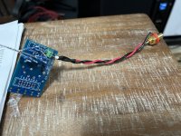
Here is a variable voltage divider that is handy for measuring a wide range of power output. I built one for my test rig.
Akitika Attenuator
The variable attenuator is handy because apparently the Focusrite's distortion is at its lowest when the gain control knob is set at approximately 11 o'clock. So as the input voltage increases, dial in more attenuation with the attenuator.
Last edited:
^ Thanks Ben! Greatly appreciated.
Your timing and recommendations are impeccable, as always. I literally just cobbled most of one of those together. I just checked it for functionality, and ... knock wood, so far, so good. Truly appreciated. Trying to hunt down an Autoranger. I may have a lead.
I need to add the LEDs (maybe) and the output jack along with giving it some stability in a case of some type... make sure nothing can short, and done...
I perhaps should have used a higher rated switch. Of course I found a more appropriate one an hour after I started building it... LOL...
Used some leftover bits from my Iron Pre.
If you don't mind...
I read your comments re: the mic input. How do you connect from the variable divider (+ and - out) to the mic input of the Focusrite? Do you use 1/4" or XLR? If you use XLR, would you mind sharing how it's wired?
Thank you!!!
Edited to add - The terminal block is temporary. 🙂
Attachments
Definitely use XLR as the XLR input has much lower distortion.
RCA + to XLR pin 2. RCA ground to XLR pins 1 and 3. Best to use shield cable for lowest noise. I connected ground wire and shield to RCA ground and to XLR pins 1 and 3.
I must add, Autorangers are for Sissies. 🙂
Edit: I checked my cable and I actually have the Neg wire connected to XLR 3 and the shield to XLR 1. I don't know whether this would be different from connection both Neg and shield to pins 1 and 3 as the Neg and shield are connected together at the RCA ground.
Last edited:
Thank you!!!! I feel so much better knowing I had planned it properly. I don't mind making the the occasional custom cable, but since I did it properly the first go around, I don't have to remake it.
Yep... a bit ol' fat fraidy cat, sissiy-pants, dodo, right here. I wear the badge proudly. 🙂
Yep... a bit ol' fat fraidy cat, sissiy-pants, dodo, right here. I wear the badge proudly. 🙂
With a measurement that uses the soundcard as signal generator, then it can be a benefit to lock the signal frequency to the RTA FFT. Also if the focus is on harmonic distortion levels and characteristics, then it can be a benefit to use coherent averaging. I'd recommend reading the help on those two items, and then playing with them to better appreciate when and why they can help.
^ Thank you! I've added that to my notes for reading and experimentation. Much appreciated.
This is an incredible piece of software with a lot of features to learn.
This is an incredible piece of software with a lot of features to learn.
I would agree with that assessment. I measured around -150db last year with Viktors oscillator. I built it into a small aluminum box and powered it with 4 9 Volt batteries in series. Added a 10-turn pot with a vernier dial for fine-tuning the output level. I can't recommend it enough!It’s so low that you can’t see what its harmonic profile is. That is, what you measure is the loop back of the ADC harmonic profile. Maybe someone has used a high gain low distortion and low noise amp to measure the oscillator?
It’s below -150dB harmonic distortion at 1kHz.
https://www.diyaudio.com/community/...ion-measurements-with-rew.338511/post-6969353
Thanks! I like nice aluminum boxes for test equipment. I posted some pics here a couple of years ago: https://www.diyaudio.com/community/...ion-measurements-with-rew.338511/post-6797064
I am looking for advice and help for some issues with a new laptop and REW / Focusrite.
All of this is likely user error of some sort, but I think there could also be some hardware and/or driver issues.
The laptop is a Framework 13 running Windows 10 with latest updates and patches.
The issue is some sort of 'glitching' with the signal over USB and REW shutting down due to errors. I believe all the data for the errors was sent to the REW team automatically when I closed REW, but I am not certain. If I can reproduce the error messages, I am happy to copy and send any logs. I don't understand them, but even when running ASIO, it was showing a Java error.
I have narrowed it down (I think) to the new laptop because everything seems to work flawlessly on a desktop.
I bring up the model of the laptop because it has interchangeable I/O slots. I've tried both USB-A and USB-C connections to the Focusrite and the behavior stays the same.
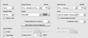
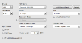
What is it doing? We can't attach video files, but I have taken a standard .mov file and zipped it for attachment. I've also attached the settings I used.
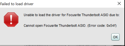
I tried using both JAVA and ASIO over USB. ASIO over thunderbolt produces an error message.
Everything looks fine, but then all of a sudden it 'glitches'. I originally thought it was picking up a system beep or sound, but I shut all of those off. I'm at my wits end.
I switched ports on the computer thinking one set may be on a different controller ... or something... I truly am shooting in the dark at this one.
Thank you in advance for any insight / clues as to where to look next. I've spent two hours trying to troubleshoot it... no luck.
Patrick
All of this is likely user error of some sort, but I think there could also be some hardware and/or driver issues.
The laptop is a Framework 13 running Windows 10 with latest updates and patches.
The issue is some sort of 'glitching' with the signal over USB and REW shutting down due to errors. I believe all the data for the errors was sent to the REW team automatically when I closed REW, but I am not certain. If I can reproduce the error messages, I am happy to copy and send any logs. I don't understand them, but even when running ASIO, it was showing a Java error.
I have narrowed it down (I think) to the new laptop because everything seems to work flawlessly on a desktop.
I bring up the model of the laptop because it has interchangeable I/O slots. I've tried both USB-A and USB-C connections to the Focusrite and the behavior stays the same.
What is it doing? We can't attach video files, but I have taken a standard .mov file and zipped it for attachment. I've also attached the settings I used.
I tried using both JAVA and ASIO over USB. ASIO over thunderbolt produces an error message.
Everything looks fine, but then all of a sudden it 'glitches'. I originally thought it was picking up a system beep or sound, but I shut all of those off. I'm at my wits end.
I switched ports on the computer thinking one set may be on a different controller ... or something... I truly am shooting in the dark at this one.
Thank you in advance for any insight / clues as to where to look next. I've spent two hours trying to troubleshoot it... no luck.
Patrick
Attachments
Last edited:
- Home
- Design & Build
- Software Tools
- How to - Distortion Measurements with REW