It’s been years since i soldered inside this amp so I’ve opened her up to conclude how it’s done.
First. The signal gnd (cleen) is directly connected to chassi (IEC) earth.
Second. There is a delay-pca connecting 320V (secondary) centertap to signal gnd 30 seconds after power switched on.
Input RCA is corectly done with only one conection to signal gnd.
Finally I found that the output transformer (speaker terminals) where floating, not tied to signal gnd.
So, with that I have two task to try.
Tie opt secondary to signal gnd and to separate signal gnd and chassi earth, as sugested.
Thanks all
Attachments


I realise that this amplifier has a lot of short comings. This is not how I would built it if I built it from scratch. With that said, I would not jeopardise any one elses health with it.Pixworld, did you realise how unsafe that mains protective earth connection could be?
It was given to me by a friend who inherited it from a friend who died (not caused by this amp…) and I figured I could fix what was missing to get it up and running.
The exposed anode voltages at the opts are not good and could easily be touched by humans or animals. However, this amp is one of many I have in my possession. It is used under very controlled moment and is not left exposed for long periods.
One day, I’ll might put it apart and rebuilt it the way I want it. But for now. It was just one way of testing the fft-measure procedure.
Thank you for your comment.
Unfortunately no improvement after adding the NTC between Earth and signal gnd. Tie opt secondary to gnd didn’t make any difference either.
Even though the 2A3 filament current is balanced out to unhearable levels with my high sensitivity horns, I can’t stop being suspicious that this is where the 50/100/150/etc peak came from.
I’ll let it rest for some days. And when I’m in the right mode, I’ll try to change it from ac- to dc filament power.

The locations of the power supply grounds to the ground bussbar are ciritical. All of the power supply grounds should not be made a one point. The dirtiest ground should be located at the starting end of the bussbar and subsequent power supply grounds should be place progressively along the bussbar.

Can you show updated REW spectrum measurements as per post #1905 to elaborate on your comment ?Tie opt secondary to gnd didn’t make any difference either.
I assume you have added a link from the OPT secondary to the 0V busbar at the location where the input sockets are connected to the 0V busbar, as that would avoid any measurement also picking up stray noise along the 0V busbar, and allow your laptop and soundcard and signal/measurement connections to have only one point of electrical contact to the amp, and to have no mains loop connection, and leave only radiated transfer of hum into your measurements setup wiring loops as suspect.
With the speaker probe connected to the input, and the amp on, then you hopefully measure something like the loopback response in post #1905.
To my mind that would then remove any chance that you measurement setup is somehow adulterating your subsequent plots of background hum. You can then use measurements to highlight changes when modifying your power supply configuration as per Ben Mah's comments. You could take the HT CT directly to the first filter cap negative link to 0V busbar. Perhaps take another photo of that region showing also the rectifier valve socket and connections.
One problem with the busbar is that one channel appears to pull all its signal current from near to the last filter cap, but the other channel requires its large signal current to pass around the bus and past the input connections.
I think the photoes indicate the input sockets have central spigots which have been left unconnected ?
@trobbins
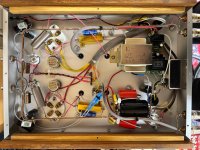
The opts secondaries are conected to the 0V busbar end (were PSU caps and conection to iec-earth (via a 5R NTC) is connected. The rca inputs are in the amplifier front and the speaker outputs/opts are in the back, hence they had to be conected 20cm appart on the busbar. Othervise a 20cm long cable had to be used, and I gather the 5mm2 thick busbar is a better alternative.
Previously it had a startup delay unit, connecting the PSU gnd to the busbar after 30 seconds. I’ll removed this unit and connected HT gnd directly to the busbar where the first PSU cap is grounded.

The input rcas (cold) are grounded directly to the busbar with short wires.
The spigots you saw was old solder. The real conection is on the lower side of the connector.

I doulechecked the hum canceling pots for the 2A3 AC heaters. But in this procedure I’ll tried to move the pots, to see if an unbalancing could influence the unvented peaks. However, this didn’t change anything.
The rectification of this amp were initially done with a 5U4 tube. However the HT was a bit on the low side so I changed this tube for silicon diods. The PSU filtering values are a bit hard to see without tearing the parts apart, but I can see that it is a C(20uF) - L(10H) - C(100uF) - R (?) - C(100uF). The last two C stages has additional PP- and mica- caps parallel to it,

With all this done I can’t see any obvious improvements in measured values.
This is measured with amp turned on, but no 1KHz stimuli.
I’m not sure if the absolute values are calibrated, but the 50 Hz peak are in the range of 4-5mV.

This measurement is done with 1KHz stimuli on and 1W output to a 8 Ohm load. The 50 Hz peak is still in the -50 dBc range.

The opts secondaries are conected to the 0V busbar end (were PSU caps and conection to iec-earth (via a 5R NTC) is connected. The rca inputs are in the amplifier front and the speaker outputs/opts are in the back, hence they had to be conected 20cm appart on the busbar. Othervise a 20cm long cable had to be used, and I gather the 5mm2 thick busbar is a better alternative.
Previously it had a startup delay unit, connecting the PSU gnd to the busbar after 30 seconds. I’ll removed this unit and connected HT gnd directly to the busbar where the first PSU cap is grounded.
The input rcas (cold) are grounded directly to the busbar with short wires.
The spigots you saw was old solder. The real conection is on the lower side of the connector.
I doulechecked the hum canceling pots for the 2A3 AC heaters. But in this procedure I’ll tried to move the pots, to see if an unbalancing could influence the unvented peaks. However, this didn’t change anything.
The rectification of this amp were initially done with a 5U4 tube. However the HT was a bit on the low side so I changed this tube for silicon diods. The PSU filtering values are a bit hard to see without tearing the parts apart, but I can see that it is a C(20uF) - L(10H) - C(100uF) - R (?) - C(100uF). The last two C stages has additional PP- and mica- caps parallel to it,
With all this done I can’t see any obvious improvements in measured values.
This is measured with amp turned on, but no 1KHz stimuli.
I’m not sure if the absolute values are calibrated, but the 50 Hz peak are in the range of 4-5mV.
This measurement is done with 1KHz stimuli on and 1W output to a 8 Ohm load. The 50 Hz peak is still in the -50 dBc range.
Are the power supply capacitor grounds and power supply ground to chassis as what I suggested in post #1926?
Where is the speaker ground connected to the buss bar? I see two black wires at the speaker negative terminal. The speaker ground should connect to the buss bar at after the last power supply capacitor. Where is the second black wire connected? I do not see a need for a second connection.
OK, I see that the second black wire connects to the other channel speaker ground connector. It is a small thing but I suggest connecting the other channel speaker ground directly to the buss and keep the ground wire away from the AC/IEC connector.
I do not see a ground loop breaker circuit between the power supply ground and chassis/power line ground. I do see the power supply ground still connected at the "dirty" end of the buss bar, not at the "clean" end.
Last edited:
Perhaps we should start a separate thread to address the noise and hum issues of this tube amp as this thread really is to discuss use of REW for measurements. Now that REW has shown that the noise floor is really dirty and full noise, let’s debug in a different thread. It is interesting for sure. The noise floor reminds me of the time I was working on Pass M2 and the onboard signal transformer was picking up a lot of mains EMI from the toroidal trafo nearby. The noise went away when I moved the trafo outside of the chassis or switched to a SMPS.
Noise floor looked like this:

I am observing a strange low level "forest" of noise on the FFT's of my amps using a linear power supply. It is not limited to just this amplifier, currently a Pass M2. I am using a toroidal 400VA 18VAC transformer (Antek) and using the two secondaries tied with a common to make +/-24vdc rails with two separate rectifier bridges and CRC filters. Rectifiers are made using 10A1 diodes in full-wave bridge. Right after diodes are two 330pF 1000v ceramic caps with 10R (0.5W) resistors to GND on each rail as snubbers (not optimized). Then 33,000uF 25v caps per rail with qnty 4 x 0.47R (2w)...
- xrk971
- Replies: 227
- Forum: Power Supplies
Noise floor looked like this:
I see a direct benefit if pixworld can present a set of REW plots that are based on a valid plot of noise floor, as that then allows confidence in interpreting subsequent before/after plots for noise floor improvements or distortion measurements. The path taken to show a valid measurement setup noise floor is imho worthwhile as that seems to be an issue that besets a few when it comes to displaying low level harmonics.
At the moment afaik, pixworld's most recent plot in post #1928 may include noise due to a ground loop related to signal input and speaker output via the internal busbar. The OPT secondary is only being used for speaker connection, so it can be linked to the busbar by any low signal wire as that wire won't carry speaker signal, and would only carry parasitic currents from internal transformer capacitances, as well as avoiding a floating speaker output and any safety risk related to that aspect. So imho, linking the speaker circuit over to the input signal point of connection to the busbar avoids any busbar noise polluting the REW plot when the soundcard/PC is all floating. And making the effort to take a baseline plot with soundcard output and input connected to the amps input only then provides a fair assurance that nothing else is polluting the measurement noise floor.
At the moment afaik, pixworld's most recent plot in post #1928 may include noise due to a ground loop related to signal input and speaker output via the internal busbar. The OPT secondary is only being used for speaker connection, so it can be linked to the busbar by any low signal wire as that wire won't carry speaker signal, and would only carry parasitic currents from internal transformer capacitances, as well as avoiding a floating speaker output and any safety risk related to that aspect. So imho, linking the speaker circuit over to the input signal point of connection to the busbar avoids any busbar noise polluting the REW plot when the soundcard/PC is all floating. And making the effort to take a baseline plot with soundcard output and input connected to the amps input only then provides a fair assurance that nothing else is polluting the measurement noise floor.
Not sure when John M added the action function "Set from RTA" to the 'Add harmonic distortion' feature of the Sine tone generator in REW, but I just had my first play of that function. Some years back I had manually 'tuned' the harmonic magnitudes and phases to minimise harmonic distortions into the noise floor when trying to deduce how low I could get THD from my EMU0404, and see how near I could get my soundcard to a 'poor mans' version of Victor's 1kHz oscillator.
To John's credit, the 'Set from RTA' does an excellent job at automating the process of adjusting residual harmonic magnitudes and phases to give the best THD performance capable from a soundcard, or test jig in loopback. I'd anticipate this could lower your test system's distortion level by 10-20dB for fixed frequency/level measurements on equipment.
I doubt there is enough usage of this feature to suggest to John if it was practical or achievable to insert this automation feature into the basic sweep measurements like THD versus level, and THD versus frequency. I'd anticipate REW could do an initial 'calibration' sweep using a loopback, followed by the defined sweep on some equipment, whereby the final sweep includes the minimised harmonic sinewave for each level or frequency defined in the sweep setup.
It's easy to see the benefit of this process for a sweep by initially setting the harmonics for a particular frequency or level, and then doing a sweep that passes through or finishes at the initially optimised level or frequency, as a nice dip in the sweep plot occurs at the optimised parameter.
Hi, I've seen this test in STEPS, but is it also available in REW?like THD versus level
Yes REW has a Stepped Measurement function in its RTA section. It can do a definable set of steps to plot THD vs Frequency, THD vs Level, IMD vs Level, and Multitone THD+N vs level. I guess like ARTA, the use of steps rather than a continuous sweep can achieve a lower noise floor for each step, and hence allow better discrimination of harmonic and IM distortion levels.
And its within that context I was interested to appreciate whether the base level harmonics/THD of the soundcard could be suppressed using the 'add harmonic distortion' feature and the 'Set from RTA' feature. Perhaps as an automated precursor calibration (using a loopback phase) to collate adjustment harmonics relevant to each step, and then automatically adjust each final measurement step to suppress inherent harmonic distortions in the test setup. REW already allows the option for such steps to be calibrated using the existing calibration file mechanism.
And its within that context I was interested to appreciate whether the base level harmonics/THD of the soundcard could be suppressed using the 'add harmonic distortion' feature and the 'Set from RTA' feature. Perhaps as an automated precursor calibration (using a loopback phase) to collate adjustment harmonics relevant to each step, and then automatically adjust each final measurement step to suppress inherent harmonic distortions in the test setup. REW already allows the option for such steps to be calibrated using the existing calibration file mechanism.
I am trying to setup a measurement rig with rew and using iD4 mk1 interface. This is the reading I am getting without any connections to input and output

And this one when connecting the output to the input directly using a cable ( no load is used ), and using the signal generator of REW

Is the noise floor too high? or is it because some setup issues?
And this one when connecting the output to the input directly using a cable ( no load is used ), and using the signal generator of REW
Is the noise floor too high? or is it because some setup issues?
The noise seems low. However dBFS for the vertical scale will the information easier to understand.
Good idea to keep playing around with settings and options, to better appreciate what they are doing, and to re-read the help sections when selecting options. One important aspect is to select use generator for fft, and use coherent averaging, and play with averaging settings.
With regards Amplifier distortion measurements, using an external USB soundcard, using a 1khz tone.Is it possible to create an error correction calibration file profile for the soundcard being used? So, if a soundcard had a high noise floor with poor distortion quality, software could fix the errors, in much the same way as the realistic sound Meter.
- Home
- Design & Build
- Software Tools
- How to - Distortion Measurements with REW