
There is a good news about ARTA SOFTWARE.
Since December 8th 2024 ARTA software version 1.9.8 is published as freeware.
This means that you can save and load your user configurations.
Download of the freeware version is <<<HERE>>>
Since December 8th 2024 ARTA software version 1.9.8 is published as freeware.
This means that you can save and load your user configurations.
Download of the freeware version is <<<HERE>>>
XiVero did this with MusicScope before they shut down. Probably a good idea to download the program now. Thanks for the post.
Stupid question.. If I use REW for distortion measurement and frequency response. Is there any reasons to use ARTA? Is there functions in ARTA generally that outperforms REW?
What result can be expected when measuring a low power SET amplifier in FFT mode?
I finally set up a rig for measuring amplifier distorsion i FFT-mode, using a Focusrite Scarlet Solo (3rd edition) and REW.
The loopback is shown below. From what I understand, it looks as it is suposed to do ? (pls. comment if not).

The DUT in this measure is a regular SET amplifier with 6072A input stage i SRPP and a 2A3 output in single end. Filamets are AC powered with ballancing pots, tuned to minimal (not audiable) hum. Output signal looks good on a scope, and visibal clipping occurs earyest at apout 3,5-4W. The sound is good with no apparent distorsion, so I would expect it to measure quite well (AC heaters and B+ hum taken into account).
However. The distorsion spectra in FFT-mode shows quite some 50Hs distorsion peaks (and 2nd, 3rd, 4th, etc overtones of it..) contaminating the hole audioband. The picture below shows the amplifier commected to the test-rig. On but with no stimuli signal put to it.
Clearly those annying 50Hz mulitpples are shown, even when no stimuli signal to the amplifier.

When stimuli-signal is put on (1kHz signal from Focusrite output) the 50Hz peaks modulates the 1KHz signal, making the whole measure quite hard to interprete. In this case the output is 1W over 8 Ohm load, so the total harmonic distorsion seems exxesivelly high (see below).
My question is. Is this what I can expect from a FFT-measure of at low power SET amplifier, or have I made someting wrong in this measure?

I finally set up a rig for measuring amplifier distorsion i FFT-mode, using a Focusrite Scarlet Solo (3rd edition) and REW.
The loopback is shown below. From what I understand, it looks as it is suposed to do ? (pls. comment if not).
The DUT in this measure is a regular SET amplifier with 6072A input stage i SRPP and a 2A3 output in single end. Filamets are AC powered with ballancing pots, tuned to minimal (not audiable) hum. Output signal looks good on a scope, and visibal clipping occurs earyest at apout 3,5-4W. The sound is good with no apparent distorsion, so I would expect it to measure quite well (AC heaters and B+ hum taken into account).
However. The distorsion spectra in FFT-mode shows quite some 50Hs distorsion peaks (and 2nd, 3rd, 4th, etc overtones of it..) contaminating the hole audioband. The picture below shows the amplifier commected to the test-rig. On but with no stimuli signal put to it.
Clearly those annying 50Hz mulitpples are shown, even when no stimuli signal to the amplifier.
When stimuli-signal is put on (1kHz signal from Focusrite output) the 50Hz peaks modulates the 1KHz signal, making the whole measure quite hard to interprete. In this case the output is 1W over 8 Ohm load, so the total harmonic distorsion seems exxesivelly high (see below).
My question is. Is this what I can expect from a FFT-measure of at low power SET amplifier, or have I made someting wrong in this measure?
I remember there was a tick box in the FFT mode that would take the measurements only after the fundamental, I don't know maybe it was another program!My question is. Is this what I can expect from a FFT-measure of at low power SET amplifier, or have I made someting wrong in this measure?
BTW your measurements seperate THD from noise and it is detecting fundamental as number one. So it seems PSU noise is high and more filtering is needed. About the THD I think 1.18% is a not bad result for a 2A3 SET at 1W, and it's nearly all 2nd order. I think it's the main characteristic of SET sound.
Last edited:
Yup pixworld, thats what you can get. Looks about right.
You need to beef up power supply filter caps.
You need to beef up power supply filter caps.
Pixworld, perhaps need to check if mains hum loop is not invading your plot. Do you have a laptop and can run laptop and soundcard and REW from battery and isolated from mains?
I had a similar result and after a few weeks of confusion I realised the outlet I was powering my rig with was not grounded (earth not wired to the main circuitbreaker)!
+1 to thatrun laptop and soundcard and REW from battery and isolated from mains
Yes, These measures were taken with my laptop and soundcard runned on batteries. Only the DUT were connected to the mains.Pixworld, perhaps need to check if mains hum loop is not invading your plot. Do you have a laptop and can run laptop and soundcard and REW from battery and isolated from mains?
Thank you all for your replies 🙂
What is your amp’s PSU setup like? What you see is typical but could be cleaner - look for radiated mains EMI contaminating your high impedance front end. Don’t place linear trafo so close to amp board. Use proper grounding strap from chassis heatsink to star earth ground connected to IEC ground. Use a ground loop breaker 10ohm NTC or resistor between chassis ground and amp analog 0v ground.
50Hz peak should be in -80dB range or lower else hum will be bad.
The SET FFT looks fine.
50Hz peak should be in -80dB range or lower else hum will be bad.
The SET FFT looks fine.
Component layout, power supply layout/ground scheme, wire layout/loop area affect level of noise.
Hard to say with this amplifier without seeing it and its construction details.
As others have commented the audio signal FFT looks in the ballpark for a 2A3 SET amplifier.
Hard to say with this amplifier without seeing it and its construction details.
As others have commented the audio signal FFT looks in the ballpark for a 2A3 SET amplifier.
Thanks xrk
It’s a regular PSU (c-l-c filter). Nothing fancy, but surely possible to make better.
Your advice to make it below -80dB was a helpful limit to aim for.
What’s most important for me in this stage, is the conclusion that the measures fft values was to rely on.
The next step will be to improve the topology.
I’m understand that it’s no easy question to answer, but I keep wondering how much of those 50Hz peaks coming from ripple at B+. And how much coming from AC filament current.
But that an easy test for me to do attaching dc sources.
Perhaps one more ground loop check would be related to the amp itself and if the signal input gnd to the amp is not the same node as the output signal gnd that is being probed and measured.Yes, These measures were taken with my laptop and soundcard runned on batteries. Only the DUT were connected to the mains.
Thank you all for your replies 🙂
Ripple is 100Hz.
50Hz from the AC filament is possible. 50Hz is also possible from EMI from AC line and power transformer. Layout and location of AC line and transformer may be factors. There are also 100Hz noise and harmonics that are high.
Views of the amplifier and including its under chassis may offer some ideas.
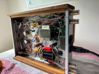
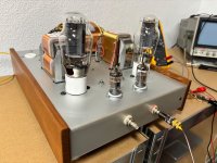
The inside is not the best looking one..
I’ve inherited this amp as as half completed build. Just finishing what’s missing. So I have not every detail in it.
The ground rail is running from iec-input to all signal grounds. What’s a bit odd is the startup timer board, connected on the ground side.
The rca inputs are on the front. And PSU in the back.
Attachments
Perhaps a photo of underside showing how the speaker winding is connected to the 0V busbar, and how the input sockets are connected to the busbar. I'm assuming the speakers are connected to 0V ?
You want to separate earth ground (dirty) from analog ground (clean) using something like CL-60 or 8D-20 NTC. Connect earth ground from IEC shell to chassis metal star point. Connect NTC between chassis star to clean ground bus bar. Ensure that RCA ground is not connected to chassis directly (this often happens with cheap non-isolated connectors). Get isolated ones with bushings or polymer bodies to ensure signal input ground does not to touch chassis directly. This will be major source of hum and ground loops.

- Home
- Design & Build
- Software Tools
- How to - Distortion Measurements with REW