According to Heinzel & Rüdiger:
https://www.researchgate.net/public...indows/link/5560ec7f08ae86c06b64a924/download
for each spectral window there is an optimal overlap factor when averaging individual spectra.
For the Blackman Harris 7 window it amounts to 87.5%.
https://www.researchgate.net/public...indows/link/5560ec7f08ae86c06b64a924/download
for each spectral window there is an optimal overlap factor when averaging individual spectra.
For the Blackman Harris 7 window it amounts to 87.5%.
"Real" numbers are numbers reported by others. What 'real' numbers have you seen, and how were they reported?hi, need some help
what kind of windowing should be used to get closer to real THD+n distortion numbers?
I'll add a button on the RTA image capture dialog to insert the settings in the comment.Just take note of the settings - and a good way is to show the settings dialog box on your screenshots so we know how much averaging, etc.

"Real" numbers are numbers reported by others. What 'real' numbers have you seen, and how were they reported?
SMSL was tested on ASR forum.
not that it's absolute best measurement that can be found, but it's good enough reference for me. one thing that differs for mine results is higher 2nd and 3rd harmonic (~6dB), but that can be result of ADC's low impedance. i wasn't able to obtain 4Vrms at SMSL output (-0,5dBfs resulted in 3.15Vrms at output). will check 'pre mode' results later.
my mystery with higher that awaited results solved 🙂
i've used 'coherent averaging' option -> as per REW's manual: "The noise level drops by about 3 dB for each doubling of the number of averages."
i've used 4 averages for above results and got ~ -123dB THD+n; with 16averages i've landed close to ~ -128dB THD+n 🙂
no coherent averaging -> ~ -118dB @-0,5dBfs generator level
Noise remains correct since 5.20.13, REW now uses separate magnitude averaging for those.The THD is accurate with coherent averaging but the noise is not accurate.
First seemingly reasonable distortion measurement with REW! Looks OK for my F5, though I obviously have some mains hum and associated harmonics to sort out.
I’m excited to test all of my amps!
I’m excited to test all of my amps!
Attachments
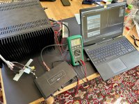
So i bought this rather new Topping E30II, was to curious not to and it could be this was my own Xmas present 
I find this very amousing actually to see with own eye's and equipment 🙂
I decided to take some measurement of the Topping, as a reference to my modded Behringer and Twin-T passive notch.
The Audiosciencereview showing sinad (THD+N) of -117dB. @ USB input.

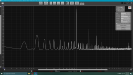
First measurement showing direct from Topping into the balanced input on my modded Behringer.
THD+N is showing -101dB (Which is rather far from Audiosciencereview Amir's -117dB)
- But it's clearly showing some very good result's comming from the Topping.

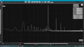
Now with my passive 1KHz notch and calibration file applied. (Red curve is calibration file)

Showing a better THD+N @ -105dB, but still 12dB from Audiosciencereview's.
I'am sure that if i used some very high grade active notch i could end up near -117dB, but due to component shortage and price increasing, i find it to expensive to build one at moment.
LEFT channel notched:

RIGHT Channel notched:

Just for the fun of it i also tried measuring two of the DAC filter's (Outputfilter 2 is the default)
Outputfilter 2:

Here is the DAC filter 1:

Jesper.
I find this very amousing actually to see with own eye's and equipment 🙂
I decided to take some measurement of the Topping, as a reference to my modded Behringer and Twin-T passive notch.
The Audiosciencereview showing sinad (THD+N) of -117dB. @ USB input.
First measurement showing direct from Topping into the balanced input on my modded Behringer.
THD+N is showing -101dB (Which is rather far from Audiosciencereview Amir's -117dB)
- But it's clearly showing some very good result's comming from the Topping.
Now with my passive 1KHz notch and calibration file applied. (Red curve is calibration file)
Showing a better THD+N @ -105dB, but still 12dB from Audiosciencereview's.
I'am sure that if i used some very high grade active notch i could end up near -117dB, but due to component shortage and price increasing, i find it to expensive to build one at moment.
LEFT channel notched:
RIGHT Channel notched:
Just for the fun of it i also tried measuring two of the DAC filter's (Outputfilter 2 is the default)
Outputfilter 2:
Here is the DAC filter 1:
Jesper.
Even with very high grade active notch your ADC will probably be a bottleneck for measuring -117dB THD+N. IME only ES9822PRO is up to the task.Showing a better THD+N @ -105dB, but still 12dB from Audiosciencereview's.
I'am sure that if i used some very high grade active notch i could end up near -117dB, but due to component shortage and price increasing, i find it to expensive to build one at moment.
Yes... you are probably right here...Even with very high grade active notch your ADC will probably be a bottleneck for measuring -117dB THD+N. IME only ES9822PRO is up to the task.
But with some shorter cables, lowering the output to -3dB (with corrected fundamental ofcause) and moving stuff a bit around, i'am reaching nearly -110dB now.
Jesper.
I'm just putting my toe in the water for all this so thanks, this is a great thread. I'm beginning to understand how to measure and attenuate the output from the speaker terminals. But what if I wanted to get an FFT profile of the output of a tube driver stage within the Amp, just ahead of the power stage? Where the driver tube plate connects via a coupling capacitor to the power stage. The voltage swing may be in the hundreds of volts at that point. Should I just attach an oscilloscope differential probe to that point to knock the voltage down 100:1 or even 500:1, then take that as the output to be measured? My goal is to view the 2nd harmonic percentages by stage to see how each stage cancels or reinforces harmonics. So for a three stage tube amp measure stage 1, stage 2 then the final after the output transformer. To see harmonic percentages at each point.
Am I on the right track for how to hook up into a high voltage stage, by using a differential probe or maybe just a regular 100:1 probe? Has anyone used these techniques on hundreds of volts swing?
Anyway, I have to learn basics first, the difficulty of getting this all down will go a long way, I've been putting it off for too long. Post #1 of this thread is a very fortunate thing considering I had no clue how to do software/interface testing like this, but knew I had to learn it sometime.
I'd strongly suggest you probe after the coupling cap to the output stage (ie. the voltage across the grid leak resistor in a cathode biased output stage) - that voltage can easily get to 50Vrms for larger amps, and may be a negative dc for fixed bias. Even then a 10:1 probe is a minimum, and I'd recommend using a 100:1 probe so that the input impedance of the probe doesn't have a significant affect - although you will need to use a cal file to normalise the frequency response, especially if going out to 96kHz.
Imho, never try and probe high dc voltage anodes if you don't have to.
Imho, never try and probe high dc voltage anodes if you don't have to.
I'd strongly suggest you probe after the coupling cap to the output stage (ie. the voltage across the grid leak resistor in a cathode biased output stage) - that voltage can easily get to 50Vrms for larger amps, and may be a negative dc for fixed bias. Even then a 10:1 probe is a minimum, and I'd recommend using a 100:1 probe so that the input impedance of the probe doesn't have a significant affect - although you will need to use a cal file to normalise the frequency response, especially if going out to 96kHz.
Imho, never try and probe high dc voltage anodes if you don't have to.
Thanks! I definitely wasn't looking to send DC into the DAC so basically across the grid leak, if it were a direct coupled stage I'd add a capacitor. I thought a 100:1 probe would be the way to do this but best to ask.
Nice setup, but for a better THD+N (or SINAD) you should use some LNA (low noise amplifier) after the passive notch filter to raise the noise floor above ADC noise. There is a nice instrument amp in your UMC202HD so you could use it (if your mods allow it...).Showing a better THD+N @ -105dB, but still 12dB from Audiosciencereview's.
I'am sure that if i used some very high grade active notch i could end up near -117dB, but due to component shortage and price increasing, i find it to expensive to build one at moment.
Martin
- Home
- Design & Build
- Software Tools
- How to - Distortion Measurements with REW