Next is to measure the distortion of my M2X using all the different daughter cards and adjust 2nd harmonic of the Isikawa RV1 adjustment.
Regarding the suspicious hump in 2nd order distortion between say 20 and 100 Hz shown with my Focusrite 2i2 in posts #54, 57, and 58:
As I said, I looked through the audio settings of my Win7 ThinkPad and didn't find anything - unchecked everything that could be suspicious, but no change.
I also did a loopback with ARTA, and it did show the same 2nd order distortion hump. So it probably does not have anything to do with REW.
To investigate further, I installed REW on a 2013 iMac as well and did some loopbacks - same behaviour on the Macintosh as well. So it's probably also not Windows-related.
Right now I could only conjecture that it is a region of higher distortion either in the ADC / signal generator of the Focusrite 2i2, or in its pre-amp / DAC part ...
Unfortunately, I don't have another low-distortion variable frequency signal generator ... my other signal generator, a Tektronix CFG250, is only spec'ed to -40 dB. And it still meets its spec after more than 30 years, though that isn't much of a help ... 🙄 😛
Best regards,
Claas
Hi Elwood,
Thanks for posting - please use 10dB/DIV scales next time so we can see more clearly. Also limit range to 0dB to -150dB. I am not sure why you have so much mains noise? Try running laptop on battery?
Regards,
X
Thanks for posting - please use 10dB/DIV scales next time so we can see more clearly. Also limit range to 0dB to -150dB. I am not sure why you have so much mains noise? Try running laptop on battery?
Regards,
X
Use your Mac sound card and Audacity to generate 1kHz Ref.
... I would need a low-distortion sweep signal to investigate the low-frequency 2nd order distortion hump ... 🙁

The plot thickens ...
Win7 laptop, Focusrite 2i2 used both as signal generator and analyzer.
In the earlier measurements, the signal generator had been set to -3 dbFS level and the Monitor level set to approx. 0.7V RMS analog output level. The gain of the Focusrite input had been set so that the peak was at -4 dBFS in REW's RTA. This setting has been found to produce the lowet THD and noise figures.
The sweeps done with these settings produced the ominous low-frequency 2nd order harmonic distortion hump.
Now look what happens if I set the sig gen to -18 dBFS level, input gain adjusted so that the peak is at -4 dBFS in the RTA again. (obviously, analog out is now much less than 0.7V RMS).
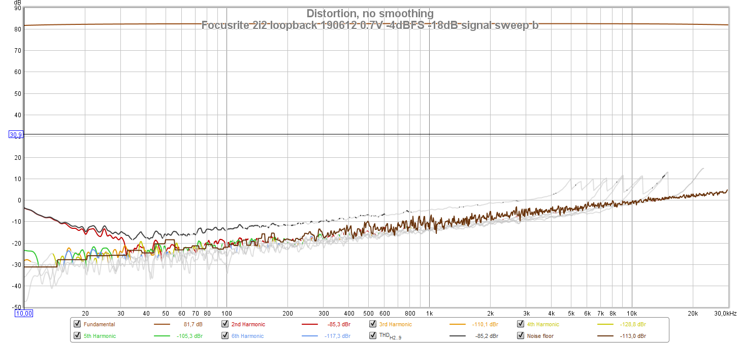
No more hump ! 😛
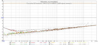
When I adjust the analog Monitor level setting to max, I gain 4.4 dB in level ... and the hump starts making an appearance again. So I still don't know if it's the Focusrite's DAC, or its analog output section, but it doesn't look like it's on the input / ADC side.
Regards, Claas
Win7 laptop, Focusrite 2i2 used both as signal generator and analyzer.
In the earlier measurements, the signal generator had been set to -3 dbFS level and the Monitor level set to approx. 0.7V RMS analog output level. The gain of the Focusrite input had been set so that the peak was at -4 dBFS in REW's RTA. This setting has been found to produce the lowet THD and noise figures.
The sweeps done with these settings produced the ominous low-frequency 2nd order harmonic distortion hump.
Now look what happens if I set the sig gen to -18 dBFS level, input gain adjusted so that the peak is at -4 dBFS in the RTA again. (obviously, analog out is now much less than 0.7V RMS).
No more hump ! 😛
When I adjust the analog Monitor level setting to max, I gain 4.4 dB in level ... and the hump starts making an appearance again. So I still don't know if it's the Focusrite's DAC, or its analog output section, but it doesn't look like it's on the input / ADC side.
Regards, Claas
Attachments
Last edited:
Right now I could only conjecture that it is a region of higher distortion either in the ADC / signal generator of the Focusrite 2i2, or in its pre-amp / DAC part ...
In that post, of course I as well meant "signal generator / DAC" for the output side and "pre-amp / ADC" for the input side ... 🙄
Regards, Claas 😉
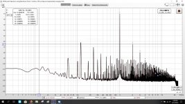
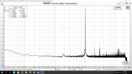
Like this?
Yes! Click on the 4 arrow cross to adjust the span.
Your PSU looks like what mine used to look like when I reported the “Forest of Noise” issue. Couple things may be going on here: you have power trafo EMI interence being coupled into the Edcor and amplified, your power trafo may be saturating due to dirty mains having DC component, and/or there are ground loops. Having 120Hz mains component only -55dB below your signal is quite audible.
But THD and profile looks consistent with what I recall.
Last edited:
I'm using 4 ohm resistors for loading both outputs, with my Fluke DMM on AC voltage, I was measuring 2 vac to the resistors. I adjusted the Akitika to get the 2vac output from the amp. Is this a correct adjustment to measure 1 watt at 4 ohms?
If the DMM measures RMS, then I'm off if peak to peak is the correct measurement.
If the DMM measures RMS, then I'm off if peak to peak is the correct measurement.
A DMM in Volts AC measures RMS assuming sine wave.
P = V^2/R so 2Vrms ^2 /4ohms = 1w
The M2X was probably not meant to drive 4ohm loads. You might try 8ohm resistor and adjust for 2.83v rms. Which is 1w rms into 8ohms.
Your loopback looks a lot better.
P = V^2/R so 2Vrms ^2 /4ohms = 1w
The M2X was probably not meant to drive 4ohm loads. You might try 8ohm resistor and adjust for 2.83v rms. Which is 1w rms into 8ohms.
Your loopback looks a lot better.
XRK how about using Siglent SDS1202X-E 200Mhz oscilloscope for measuring the FFT plot. any advice much appreciated.
here is the link for the oscilloscope Siglent SDS1202X-E 200Mhz
here is the link for the oscilloscope Siglent SDS1202X-E 200Mhz
Last edited:
Hi Suresh,
O-Scopes are different specialty tool. They are crucial for visualizing time varying or transient events. They generally have extreme speed but lower resolution. Typically 8bit or maybe 10bit ADC’s. So their resolution in terms of noise floor vs signal is not going to be very deep. With averaging turned on, maybe 50dB to 60dB range.
RF Spectrum Analyzers May work better if they have a higher resolution ADC. An audio spectrum analyzer like the one from SRS like SR1 is perhaps even better than what PC sound interfaces can do.
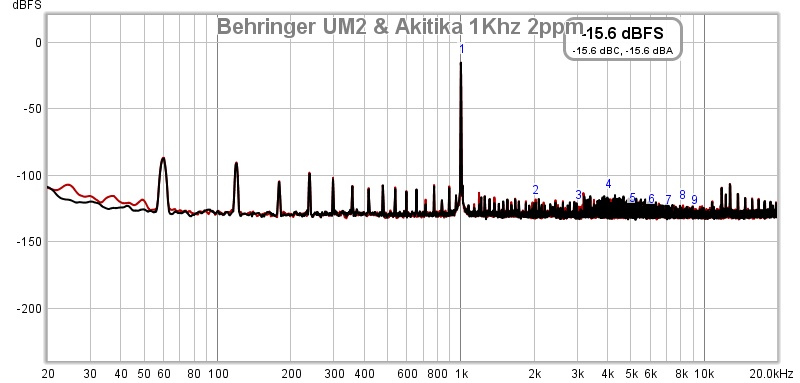
Update June 3, 2019: Here is a loopback using Focusrite Solo gen2 and Akitika 2ppm 1kHz oscillator at 1.0Vpp into 10k:
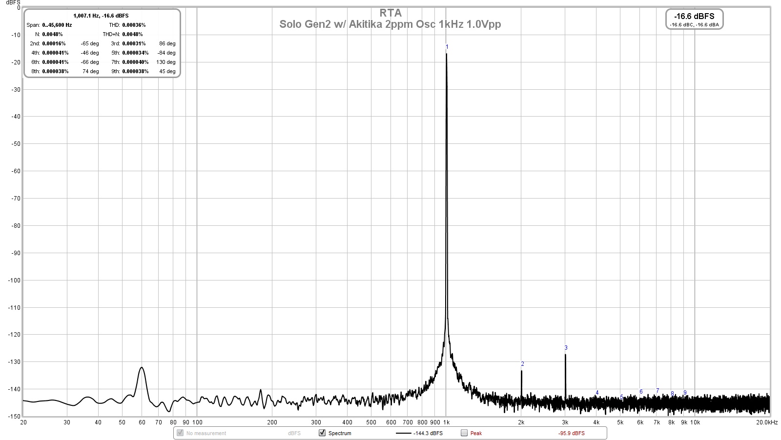
How is it possible to get 0.00033% THD when the Solo is spec'ed at 0.003%?
Using a Victors oscillator I am getting 0.0033% THD using a 1st gen 2i2 which has a THD spec of -91dB (about the same as 0.003%) at minimum gain 🙁
I've followed the instructions and settings carefully but wonder if I am doing something wrong?
The amplitude that the oscillator has to drive and the output impedance of the oscillator has an impact on the value. Make sure you are not asking an opamp of to drive a low impedance load at too high of an amplitude. 1Vpp is 0.353Vrms.
How I got a number better than factory spec? Lucky unit?
How I got a number better than factory spec? Lucky unit?
Maybe it’s not just all luck? I measured 0.00061%THD with my 2i4 and this was a headphone amp driving 47ohms - not a loopback.
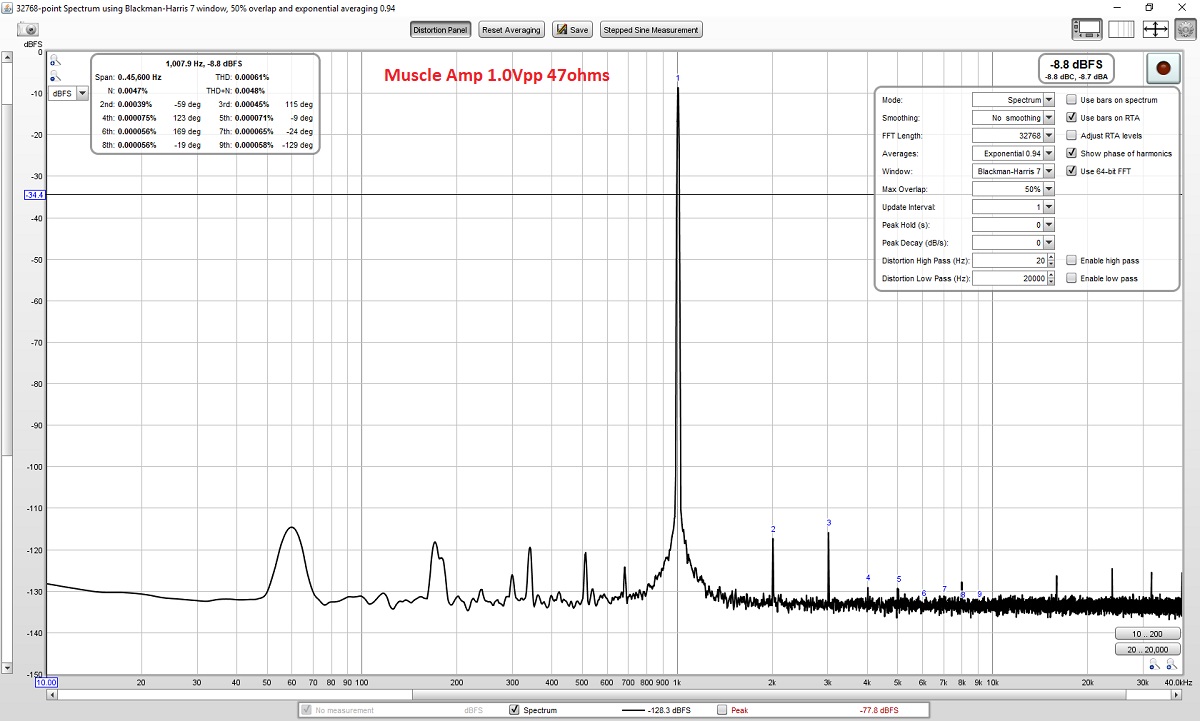
Careful attention to good quality cabling, clean connections, a quiet laptop (mine has a SSD). Mostly, make sure you are not driving any more amplitude than needed from either the oscillator or the Focusrite front end preamp.
Careful attention to good quality cabling, clean connections, a quiet laptop (mine has a SSD). Mostly, make sure you are not driving any more amplitude than needed from either the oscillator or the Focusrite front end preamp.
- Home
- Design & Build
- Software Tools
- How to - Distortion Measurements with REW