Maybe some progress
Found a mono 1/4 plug
Wire it up
Input to Line
Spectrum obtained that looks reasonable
Will explore more tomorrow
Thanks so much you guys
Found a mono 1/4 plug
Wire it up
Input to Line
Spectrum obtained that looks reasonable
Will explore more tomorrow
Thanks so much you guys
Great to hear, Bob!
All -
I did a bit of playing this morning before work. Like a kid at Christmas wanting to open and play with toys. I have to say, this hobby and this community sure do make life a bit easier.... 😀
I have always been fascinated by measurements of the "full chain". We see independent measurements all the time, but rarely if ever, do reviewers or hobbyists (that I have seen) measure components together. I have a few components between "digital signal" and speakers. 3 of them have analog stages... DAC, Pre-Amp, Amp. At some point, I want to understand a bit about how each of them contribute and more importantly how they work together. I know how they sound... I like it 😀
So, I went one step back in the chain this morning. I still have a lot to learn re: proper calibration etc. So, please don't take any of these posts as "real" measurements. My main goal was to see the overall distortion profile. I think I was successful.
I used the signal generator in REW to send a 1011 Hz signal to the ACP+ over T(R)S to RCA. I adjusted the digital signal to -20.20dBFS to yield 2V83 (ish) at amp output across the load. No analog input attenuation on the ACP+ (volume all the way up). Output of the ACP+ to the BA-3 using my normal RCA interconnect. Output of BA-3 over 4ohm load to Focusrite Input 1. No gain on the Focusrite. This was all "in place" in my normal rack, with normal wall power and with all the other zillion things plugged into the same AC circuit. 😀
Fun stuff! Thanks once again to XRK971 for kicking the interest in this phenomenal software up a notch and providing the guide. More importantly, thanks so much to John Mulcahy for providing an incredible piece of software. I have a lot to learn and a new tool in the kit. 😀
Progress I think
Guys
First apologies to xrk - I think I said xrf (old habit from years in xray research)
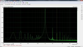
Spectrum attached
taken at 1W using line in to Solo
Best and thanks for all the help
Bob
Guys
First apologies to xrk - I think I said xrf (old habit from years in xray research)
Spectrum attached
taken at 1W using line in to Solo
Best and thanks for all the help
Bob
Attachments


Hi Bob,
looking good ! (you might be able to get narrower shoulders at your main line by integrating a bit longer)
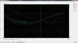
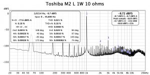
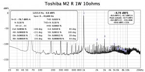
Just for comparison, here are some of my measurements for my M2, also built with Toshibas (2SJ201 / 2SK1530). The M2 has been built on JPS64's boards.
I believe these measurements also have been at 1 W. I'm not totally sure, as I seem not to have taken lab notes (duh !)
These measurements were taken with a Focusrite 2i2, albeit still with ARTA. Only switched to REW later ...
Looks like we are in the same ballpark ... 😀
Regards, Claas
looking good ! (you might be able to get narrower shoulders at your main line by integrating a bit longer)
Just for comparison, here are some of my measurements for my M2, also built with Toshibas (2SJ201 / 2SK1530). The M2 has been built on JPS64's boards.
I believe these measurements also have been at 1 W. I'm not totally sure, as I seem not to have taken lab notes (duh !)
These measurements were taken with a Focusrite 2i2, albeit still with ARTA. Only switched to REW later ...
Looks like we are in the same ballpark ... 😀
Regards, Claas
Attachments
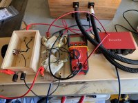
Thanks Claas for the encouragement.
I will integrate longer - my images were from 10 second snapshots. I was after proof of concept ie I may have finally figured it out. 😀
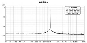
My 1kHz source which you can't see in pic is the Akitika
Best and thanks 🙂
Bob
I will integrate longer - my images were from 10 second snapshots. I was after proof of concept ie I may have finally figured it out. 😀
My 1kHz source which you can't see in pic is the Akitika
Best and thanks 🙂
Bob
Window choice is the main factor. For best resolution the generator should be set to "Lock frequency to RTA FFT" and a rectangular window used, otherwise Blackman-Harris 7 or the Dolph-Chebyshev windows will give better results.you might be able to get narrower shoulders at your main line by integrating a bit longer
I'm back at it 😀
I've read more than my brain can soak in. The "Basics" in the REW help are phenomenal, but there are still a few things I haven't nailed down.
For power measurements and/or distortion measurements where we're assuming 1W (in my case 2W with 2V83 and a 4ohm load) it's fairly simple to just use the DMM across the load resistor to ensure proper results are recorded.
However, I was wondering re: the calibration of the dBFS ouput to voltage output with the soundcard calibrated properly in settings and again with the signal generator and a DMM.
When I look at the default expectation for voltage out with a -6dBFS signal I think it was in the neighborhood of 513 mV ... I didn't record it.
When I connected the TRS (not TS) to XLR patch I use for the loopback measurements, I got 612mV across pins 1 and 2 and 610mV across pins 1 and 3. So, a bit more voltage, but no worries. I entered 611 into the calibration. Not bad phase matching, if I've interpreted it properly. However, that could easily could be my DMM too. When I connected my TS to RCA - the good news is that it confirms the exact 610mV expected.... yes, I'm still THAT slow. 😉
What I'm wondering is if I do a measurement on a balanced amp - I'll have 1V22 output from the Focusrite, correct? I'm using "both halves". So, should I enter that value when measuring a balanced amp?
I am loving learning this, but I hit a few mental roadblocks.
With thanks in advance!

Edited to add - I measured a different amp prior to making some PSU changes re: toroid orientation, tidying wires etc. The amp sounds fabulous, but compared to the BA-3 with the new arrangement - I need to get on tidying up the wiring, moving the toroids and shielding them. The PSU sections of both amps are identical except for physical treatments.... I never expected it to be that dramatic (If I'm interpreting things properly)...
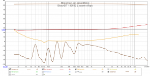
BA-3

SissySIT that (I think) clearly needs some attention paid to PSU and wire routing.

I've read more than my brain can soak in. The "Basics" in the REW help are phenomenal, but there are still a few things I haven't nailed down.
For power measurements and/or distortion measurements where we're assuming 1W (in my case 2W with 2V83 and a 4ohm load) it's fairly simple to just use the DMM across the load resistor to ensure proper results are recorded.
However, I was wondering re: the calibration of the dBFS ouput to voltage output with the soundcard calibrated properly in settings and again with the signal generator and a DMM.
When I look at the default expectation for voltage out with a -6dBFS signal I think it was in the neighborhood of 513 mV ... I didn't record it.
When I connected the TRS (not TS) to XLR patch I use for the loopback measurements, I got 612mV across pins 1 and 2 and 610mV across pins 1 and 3. So, a bit more voltage, but no worries. I entered 611 into the calibration. Not bad phase matching, if I've interpreted it properly. However, that could easily could be my DMM too. When I connected my TS to RCA - the good news is that it confirms the exact 610mV expected.... yes, I'm still THAT slow. 😉
What I'm wondering is if I do a measurement on a balanced amp - I'll have 1V22 output from the Focusrite, correct? I'm using "both halves". So, should I enter that value when measuring a balanced amp?
I am loving learning this, but I hit a few mental roadblocks.
With thanks in advance!
Edited to add - I measured a different amp prior to making some PSU changes re: toroid orientation, tidying wires etc. The amp sounds fabulous, but compared to the BA-3 with the new arrangement - I need to get on tidying up the wiring, moving the toroids and shielding them. The PSU sections of both amps are identical except for physical treatments.... I never expected it to be that dramatic (If I'm interpreting things properly)...
BA-3
SissySIT that (I think) clearly needs some attention paid to PSU and wire routing.
Last edited:
Yes, the voltages would add, but better to just measure from pins 2-3 and let the voltmeter do the addition.
You may be trying to do something more exacting than I typically do, but I've never measured the voltage going to the amp in typical distortion measurements. My measurement procedure is to:
1) set the soundcard output well below where i think it will need to be (to avoid inadvertent blowing up the amp - yes I have done that 😡)
2) turn on amp and measure output using my cheapie DMM (verified to be close enough to accurate for my needs and not grounded so nothing to worry about - yes, I've also blown up amps by grounding things that shouldn't be 😡) and inch up to my desired measurement power level - typically around 5W give or take.
3) set my soundcard input attenuator box (initially at max attenuation to avoid blowing up my souncard - never done that 😉) so that the soundcard input is at the sweet spot (in my case around -15dBFS).
Yes, the voltages would add, but better to just measure from pins 2-3 and let the voltmeter do the addition.
Thanks for the input! Cool. I appreciate the confirmation.
You may be trying to do something more exacting than I typically do, but I've never measured the voltage going to the amp in typical distortion measurements. My measurement procedure is to:
1) set the soundcard output well below where i think it will need to be (to avoid inadvertent blowing up the amp - yes I have done that 😡)
Definitely not trying to do anything exacting. I had read a few posts re: "calibrating" the dBFS levels to coincide with voltage output. Which is a nice thing to have, I suppose. If anything, it makes the dBFS charts align with voltage properly if I enter the value into the top of RTA chart. I suppose a knowledgeable person (not me) could look at a properly run chart; and if they knew the load (or if I bothered to label my graphs), and saw the dBFS readings - they could calculate the output voltage. Also.. I suppose that if it's properly calibrated, and if I knew the exact gain of the amp - I wouldn't need the DMM - but the DMM across the load is easy.
Honestly, I am not 100% sure how I will use this now or in the future, but I'm learning as I go.
re: not blowing stuff up 🙂 Definitely. I always start out with it at -30dBFS and slowly ramp up. Another confirmation of good practices always helps me. I still do a little cringe move when I hook it up...

2) turn on amp and measure output using my cheapie DMM (verified to be close enough to accurate for my needs and not grounded so nothing to worry about - yes, I've also blown up amps by grounding things that shouldn't be 😡) and inch up to my desired measurement power level - typically around 5W give or take.
Great to know. I really do need to mount my "jig" on a board of some sort. The hanging wires are a bit of a hazard. Great call! So far, I've only been brave enough to do measurements at 2V83 into 4 ohms (2W), but I did set the output on the Focusrite at 0dBFS once to see what output I'd get at the amp - a shade over 10VAC.
3) set my soundcard input attenuator box (initially at max attenuation to avoid blowing up my souncard - never done that 😉) so that the soundcard input is at the sweet spot (in my case around -15dBFS).
So far, I have not used input attenuation - I do have the fixed voltage divider just in case. It looks like -12.0/-11.9dBFS yields right at 2V83 from the amp - which may be an odd coincidence.
Thanks to ALL who helped me get started
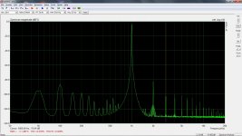
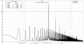
Some M2 (Tea Bag Boards) measurements.
I will keep
RTA settings as recommended in JohnPM's post
Best
Bob
Congrats! That's going to sound incredible with the new Pumpkin!
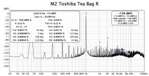
Just to see if I've learned anything... is that without Schade (because dominant H3)???
Patrick
Thanks, Claas!
I had noticed yours. Mine was/is quiet also, but it seems to have a ton of "grass" related to powerline noise and / or EMI from inside the chassis. Still new to all of this. The "noise" is higher than the 2nd harmonic. I can't believe one amp with an identical PSU in a similar configuration has that much more noise. However, I did completely re-do all the wiring for the BA. After I re-do the other wiring and shield the toroids, I'll see if it has an effect. It could also be measurement technique, or lack thereof. 😀
I had noticed yours. Mine was/is quiet also, but it seems to have a ton of "grass" related to powerline noise and / or EMI from inside the chassis. Still new to all of this. The "noise" is higher than the 2nd harmonic. I can't believe one amp with an identical PSU in a similar configuration has that much more noise. However, I did completely re-do all the wiring for the BA. After I re-do the other wiring and shield the toroids, I'll see if it has an effect. It could also be measurement technique, or lack thereof. 😀
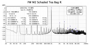
is that without Schade (because dominant H3)???
this is w/o Schade !! It uses Toshiba output devices
Here is my Schaded amp - different amp Schaded with IRFs
Not a direct comparison of course but just to give an idea
this is w/o Schade !! It uses Toshiba output devices
Here is my Schaded amp - different amp Schaded with IRFs
Not a direct comparison of course but just to give an idea
Attachments
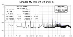

used a 3.3k Schade resistor - may tinker a bit more now that I have a tool to see results.
Also different values for Schade depending on channel ?????
Also different values for Schade depending on channel ?????
That is very cool! Thanks.
The values by channel could / would be very interesting. Is there a sought after effect, or are you just fiddling? Either way, that is something I've never considered.
The values by channel could / would be very interesting. Is there a sought after effect, or are you just fiddling? Either way, that is something I've never considered.
To my ears and in my system the Schaded M2 moves toward the SissySit in presentation and appeal The Sissy is the amp I return to.😀
I would recommend a Schaded M2 to anyone who doesn't have access to the Tokins
I would recommend a Schaded M2 to anyone who doesn't have access to the Tokins
Hi guys, anybody knows how to do an impulse response/freq response measurement in loop-back in REW? I'm sure it is simple but I can't find the right buttons to click ....
Jan
Jan
- Home
- Design & Build
- Software Tools
- How to - Distortion Measurements with REW