Practice spectrum
Attenuator set to 6dB
3.17VAC across 10 ohm load resistor
.6VAC input to Focus Solo
To get peaks in spectrum left input has to be in red -green and amber give no peaks at harmonic points
Seems to be distorted😕
In REW preferences input is Focus Solo MIC, output to Focus Solo Speakers
Thoughts?
Thank you
Bob
Attachments
Can you elaborate on what you mean, and what is shown in plot?To get peaks in spectrum left input has to be in red -green and amber give no peaks at harmonic points
Seems to be distorted😕
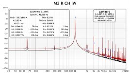
The plot shows the results of a M2amp when the gain knob on the Solo is turned so that the red led comes on
When the gain knob on the Solo is lit green there are no harmonic peaks
When it is amber there are no harmonic peaks
From the Scarlett Solo manual "the gain controls have concentric tri-colour LED rings to confirm signal level , green indicates an input level of at least -24dBFS, the ring turns amber at -6dBFS to indicate that the signal is close to clipping and finally to red at 0dBFS (digital clipping)
The attenuator is at 6dB( attenuator is the one shown a few posts previously
Thank you
Ok, so if you have confirmed that the Solo input circuitry is not contributing distortion by keeping the input gain so that input signal is not above -6dB, then the distortion is from the DUT. Is that how you understand it?
I'll generate a couple of plots tomorrow with gain level green and gain level amber
Also I can try another amp.
Thank you
Can load resistors go flakey?
Also I can try another amp.
Thank you
Can load resistors go flakey?
Not sure what amp you are testing, but that level of distortion at 1W may be nominal.
Test load resistors can generate their own distortion, as indicated in this thread, although your load resistors may be the low tempco sort, and it's likely that any load related distortion is below your noise floor for 1W output. Is that what you mean by 'flackey' ?
Test load resistors can generate their own distortion, as indicated in this thread, although your load resistors may be the low tempco sort, and it's likely that any load related distortion is below your noise floor for 1W output. Is that what you mean by 'flackey' ?
This amp is a First Watt M2 (Nelson Pass)
http://www.firstwatt.com/pdf/prod_m2_man.pdf
Indeed what I meant - grasping - I'm going to re=read the thread tonight
Thanks again
http://www.firstwatt.com/pdf/prod_m2_man.pdf
Indeed what I meant - grasping - I'm going to re=read the thread tonight
Thanks again
That amp appears to achieve much lower distortion than your measured 0.27% THD.
So yes you need to cross-check what distortion your Solo introduces (output signal, and input signal contributions) for the levels you are generating from the Solo, and recording in to the Solo, to confirm your Solo setup is not the main contributor of distortion, and then confirm how your DUT distortion changes, and investigate whether you have set your DUT up properly.
So yes you need to cross-check what distortion your Solo introduces (output signal, and input signal contributions) for the levels you are generating from the Solo, and recording in to the Solo, to confirm your Solo setup is not the main contributor of distortion, and then confirm how your DUT distortion changes, and investigate whether you have set your DUT up properly.
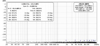
The measured fundamental at 0.1dBFs clearly shows the ADC in the soundcard is clipping and signal must be attenuated before the AD conversion. The fundamental must be negative dBFs (i.e. < 1) for the measurement to work properly.
The plot shows the results of a M2amp when the gain knob on the Solo is turned so that the red led comes on
When the gain knob on the Solo is lit green there are no harmonic peaks
When it is amber there are no harmonic peaks
From the Scarlett Solo manual "the gain controls have concentric tri-colour LED rings to confirm signal level , green indicates an input level of at least -24dBFS, the ring turns amber at -6dBFS to indicate that the signal is close to clipping and finally to red at 0dBFS (digital clipping)
The attenuator is at 6dB( attenuator is the one shown a few posts previously
Thank you
With the Solo in red you are distorting the Solo input circuit (that is why it turns red ;-) .
So with the Solo red you measure the Solo distortion, not the amp distortion.
If you don't see any distortion with the Solo on green or amber that means that the amp has less distortion than the floor of your measurement equipment.
Jan
Most probably a set-up issue ...
I agree with everybody before, Focusrite indicator ring has to be green.
I don't have a Solo, but with 2i2 I have been able to measure the M2 perfectly, see my posts in this thread.
Bob, how do your loopback measurements look like ?
- no signal, output back to input
- signal from Solo or Akitika generator (or other confirmed-low harmonic generator) back into the Solo
Try to get a graph like the ones shown here, can't pull up the ones with the recommended settings at the moment, but it was something with Blackman-Harris, 65k samples, ...
Regards,
Claas
Switched amps - same behavior
Some spectra
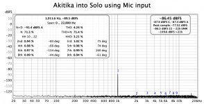
Akitika into Solo (Gen 3) through XLR input (MIC)
Solo with nothing attached
I just noticed that in post 1 xrf shows line input in figure
I have been using xlr input with cable modified as shown early in thread
Should I be using line?
I need to find TRS connectors to proceed if that is the case
Best and thanks
Bob
Some spectra
Akitika into Solo (Gen 3) through XLR input (MIC)
Solo with nothing attached
I just noticed that in post 1 xrf shows line input in figure
I have been using xlr input with cable modified as shown early in thread
Should I be using line?
I need to find TRS connectors to proceed if that is the case
Best and thanks
Bob
Attachments
I'm using line input with unbalanced TS plug.
Try to set the gain / signal strength so that you have -10 dB to -6 dB signal ... you can experiment a bit which signal level gives the best S/N ratio.
Best regards,
Claas
Try to set the gain / signal strength so that you have -10 dB to -6 dB signal ... you can experiment a bit which signal level gives the best S/N ratio.
Best regards,
Claas
Bob, I'm with ya! This is not easy for me to wrap my brain around.
All - I think I have my Mac set up properly (again), and I got my test rig built up. I gave it a whirl.
Attached are some photos of the progression.
Test jig built... Note I had to rebuild it 1/2 way through. I didn't put proper strain relief around the voltage divider resistors. Too much movement... snap. This is a pic of the first iteration. I rebuilt it to be a bit more robust and with longer leads for my ham-fisted self. 😀

I started by using an old phone and the first YouTube video that the search provided to generate the test tone. Not super. The volume control on the phone in conjunction with the volume control on YouTube is not too precise. Also, clearly the signal isn't too wonderful. All-together not a great option, but I was fiddling and trying to move in steps.


Then I used szynalski.com - much cleaner tone. I still couldn't quite get enough oooopmph from the phone signal....


So, I built a TRS to RCA. Exciting huh?! 😀

Then I used the signal generator in REW through the Focusrite into the amp. Much better... and clearly better shielding on the cable (at least that's what I think it may be) - note the lower mains components. I'm speculating, but the 3.5mm to RCA from the phone or the phone itself may have been picking up some noise. Who knows?


This is my first "real" measurement of the new BA-3 I built. Left channel. REW signal generator was set to -11.20dBFS to get 2V83 from the amp into 4 ohms. Line output from Focusrite to amp, no gain on Focusrite input.
More to learn, I still don't think it's 100% proper, but I'm getting there. 🙂
Edited to add - I had played with "P3" while using the phone as a signal generator. 😀 So, the distortion profile is quite a bit different between the 2nd and 3rd iterations.
All - I think I have my Mac set up properly (again), and I got my test rig built up. I gave it a whirl.
Attached are some photos of the progression.
Test jig built... Note I had to rebuild it 1/2 way through. I didn't put proper strain relief around the voltage divider resistors. Too much movement... snap. This is a pic of the first iteration. I rebuilt it to be a bit more robust and with longer leads for my ham-fisted self. 😀
I started by using an old phone and the first YouTube video that the search provided to generate the test tone.
Not super. The volume control on the phone in conjunction with the volume control on YouTube is not too precise. Also, clearly the signal isn't too wonderful. All-together not a great option, but I was fiddling and trying to move in steps.Then I used szynalski.com - much cleaner tone. I still couldn't quite get enough oooopmph from the phone signal....
So, I built a TRS to RCA. Exciting huh?! 😀
Then I used the signal generator in REW through the Focusrite into the amp. Much better... and clearly better shielding on the cable (at least that's what I think it may be) - note the lower mains components. I'm speculating, but the 3.5mm to RCA from the phone or the phone itself may have been picking up some noise. Who knows?
This is my first "real" measurement of the new BA-3 I built. Left channel. REW signal generator was set to -11.20dBFS to get 2V83 from the amp into 4 ohms. Line output from Focusrite to amp, no gain on Focusrite input.
More to learn, I still don't think it's 100% proper, but I'm getting there. 🙂
Edited to add - I had played with "P3" while using the phone as a signal generator. 😀 So, the distortion profile is quite a bit different between the 2nd and 3rd iterations.
Last edited:
ItsAllInMyHead
Thanks for the pics !!!
Are you using the MIC input? I have set Preferences with Input Solo MIC and output Solo Speakers.
When I do this I cant get the Solo to take any data without clipping
Best
Thanks for the pics !!!
Are you using the MIC input? I have set Preferences with Input Solo MIC and output Solo Speakers.
When I do this I cant get the Solo to take any data without clipping
Best
My pleasure.
So, here is what (I think) I know. I can't even add the 'S' to WAG
For the Mac - The Input Device is the "Focusrite itself". The "Input" is the actual physical input on the front of the Focusrite. It's telling the software "look here for the input signal". In your case, it most likely should be microphone. The inputs are numbered on a PC using the ASIO drivers.
What I have found (I think) is that the Focusrite Control software and my Mac and REW get into a fight sometimes and / or I'm a Dodo.
So, what I do is probably way too long a set up, but until I get it down...
This for an actual measurement and prep.
1) Open REW
2) Open Control
3) Make sure my "Output Routing" within Control routes the "Playback DAW" to Output 3 in my case b/c it's the line level output I use. It also mirrors the HP output.
4) Play a test tone from REW and make sure I "see it" in Control - green level indicator.
5) Loop the signal to the front panel with the TRS to XLR.
6) Make sure that my front panel light glows. I like it green if only b/c I don't know any better. I usually set the output in the generator to -12dBFS
7) Make sure I can actually see that Control shows the output signal on #3 and input level on In 1 (in my case the left input).
8) Put on the HPs on to see if I can hear it.
Note - Before I did all this, I set the output level on Out 3 within Control to -6dBFS. When I was doing my initial loopback measurements, I noticed that was the level that "matched". i.e if I feed a -12dBFS signal to the FR, I got -12.1dBFS in the RTA.
tl;dr - I have to manipulate both REW and Control to be sure everything stays where it's supposed to be. I also still don't know if I'm doing it properly.
Edited to add - Fixed some notes and my thought around "microphone" input.
- Home
- Design & Build
- Software Tools
- How to - Distortion Measurements with REW