The stability of the averaged value will depend on how stationary the noise is.Well, averaging doesn't really lower the noise floor, it lowers the noise pk to pk value, squeezes the noise, sort of*. As the noise amplitude gets squeezed, the harmonics become visible and that may be why they have some value jitter during the averaging.
But yes the final values should agree.
Maybe John when reading this can shine some light?
OK thanks, I am away from home now, so be a few days.
BTW Also just discovered your multitone generator. Another 'high end' feature to be tested!
Jan
BTW Also just discovered your multitone generator. Another 'high end' feature to be tested!
Jan
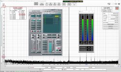
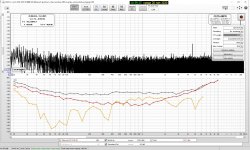
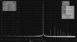
I had a play with coherent averaging for harmonic distortion measurement today, aligning phase based on the fundamental before doing a complex average, and it seems to work quite well. Non-harmonic content is strongly suppressed and here is no need for long FFTs, the example below compares a 64k FFT with coherent averaging and a 1M FFT with magnitude averaging. I'll include this in the next beta, but it should probably be treated as an experimental feature.


John, that is a very useful feature which will drastically shorten low-distortion measurements. Thank you.
Yes, very impressive result. I do see quite a difference in the # of averages, but I guess that means that the total FFT/averaging time between the two situations is comparable?
Jan
Jan
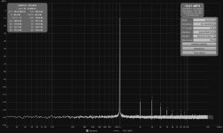
Yes, though the coherent averaging delivers benefits very quickly, about a 20 dB drop in the noise floor in the first 30 seconds on my test setup. Very much diminishing returns after that, but the level does keep dropping.Yes, very impressive result. I do see quite a difference in the # of averages, but I guess that means that the total FFT/averaging time between the two situations is comparable?

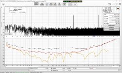
Edit: Here is how it looks after about 10 minutes of averaging:

Last edited:
John is this coherent averaging experimental or can I select it somewhere in the current version?
Jan
Jan
😱 Very impressive indeed.I'll include this in the next beta, but it should probably be treated as an experimental feature.
Fortunately, new beta versions from John are frequent.
Hi John,
is this on an AC-powered or DC-powered setup ?
I am wondering about the averaging away of the 50 Hz and 100 Hz signals with Coherent Averaging.
But, I have not looked at the mathematics behind Coherent Averaging ... only have heard of it for the first time from you these few days past 🙂
On second look: I see that you are using 997 Hz signal. Is the Coherent Averaging looking at the strongest signal in the respective data set and only "registering" signals that are harmonics of this strongest signal ?
Best regards, Claas
The time shift property of the FFT is used with a time delay corresponding to the phase of the fundamental. Say the fundamental phase in an FFT result is phi degrees, then the time shift to bring phi to zero at the fundamental is -phi/(360*fundFreq). That time shift is applied to each FFT bin as a phase rotation of bin frequency * time shift on the bin FFT result. An FFT which has been processed in that way has the fundamental at zero phase and the harmonics at fixed phases relative to the fundamental. A complex (vector) average of a series of such FFTs will then coherently sum for the fundamental and its harmonics, but anything with a random phase relationship to the fundamental will decay. It is only useful to reveal harmonics that would otherwise be lost in noise, since other content is suppressed.
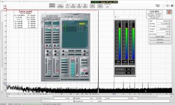
-13dBFs @88200 & 96000 @ CS4398 @ АК5394
Attachments

Hi all, first post, started reading (very) long time ago but couldn't stand anymore not beeing able to see pics !
I've been measuring THD+N on several devices using Scarlett 2i2 and for amps output, a volatge divisor on 4 Omhs dummy load. As I use this setup to improve my ClassD amp, I need to make sure my measurements make sense.
I use to always top DBSfs scale (closest possible to 0 DBfs) at 1Khz to get lowest noise and then read the THD+N result.
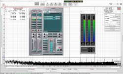
Below is my Scarlett 2i2 Gen 2 in loopback, balnced out to balanced in, output almost maxed out, input gain at approx 1/3 to reach 0 DBfs, REW generator at 0 DB, Asio4ALL. THD+N result seems consitent to me but I'd like to confirm if doing anything wrong.


I've been measuring THD+N on several devices using Scarlett 2i2 and for amps output, a volatge divisor on 4 Omhs dummy load. As I use this setup to improve my ClassD amp, I need to make sure my measurements make sense.
I use to always top DBSfs scale (closest possible to 0 DBfs) at 1Khz to get lowest noise and then read the THD+N result.
Below is my Scarlett 2i2 Gen 2 in loopback, balnced out to balanced in, output almost maxed out, input gain at approx 1/3 to reach 0 DBfs, REW generator at 0 DB, Asio4ALL. THD+N result seems consitent to me but I'd like to confirm if doing anything wrong.

Attachments
Last edited:
 Like this:
Overview and information and tests Scarlett 2i2Schmilblick
... my Scarlett 2i2 Gen 2 in loopback, balnced out to balanced in, output almost maxed out, input gain at approx 1/3 to reach 0 DBfs, REW generator at 0 DB, Asio4ALL. THD+N result seems consitent to me but I'd like to confirm if doing anything wrong.
Focusrite Scarlett 2i2 Audio Interface Gen 3 Review | Audio Science Review (ASR) Forum
The time shift property of the FFT is used with a time delay corresponding to the phase of the fundamental. Say the fundamental phase in an FFT result is phi degrees, then the time shift to bring phi to zero at the fundamental is -phi/(360*fundFreq). That time shift is applied to each FFT bin as a phase rotation of bin frequency * time shift on the bin FFT result. An FFT which has been processed in that way has the fundamental at zero phase and the harmonics at fixed phases relative to the fundamental. A complex (vector) average of a series of such FFTs will then coherently sum for the fundamental and its harmonics, but anything with a random phase relationship to the fundamental will decay. It is only useful to reveal harmonics that would otherwise be lost in noise, since other content is suppressed.
Thanks, John, for the explanation !
So the Coherent Averaging is a very useful tool to tease the harmonic distortion components out of a measurement set, by suppressing everything that is not a harmonic of the main signal - including a power supply signal and its own harmonics 😀
Best regards, Claas
Overview and information and tests Scarlett 2i2
Focusrite Scarlett 2i2 Audio Interface Gen 3 Review | Audio Science Review (ASR) Forum
Thanks, I know these, that is DAC and ADC measured separatly, using top notch device (AP) on Gen 3 version.
Now, I just realized I was using Line balanced input for loopback and Amp measurements ( Balanced TRS In) instead of MIC in (XLR). Loopback measurement this way is a tad better.
Attachments

IMO, in such case the chart could show only the fundamental-related bins, as the rest does not carry any meaningful information after several averages, IIUC.
Schmilblick
Try reducing the signal level of the generator = DAC to -10dB
Ok so here they are, first is REW generator to -10db, second is REW gen to 0db and Scarlett output knob adjusted down (Scarlett input gain always set to minimum).
But then how can I assess noise performance if I don't measure at 0dbFS ? isn't that relevant for THD only ?
Attachments

- Home
- Design & Build
- Software Tools
- How to - Distortion Measurements with REW