Has someone done thd , thd+n and IM distortion measurements for a dac with a soundcard that has digital output to dac or what is the recommended measurement approach.
Dac measurements require very good souncard that the soundcard loopback distortion result is better than the dac distortion level. My cable package from ebay germany is still on the way so no measurements yet. Here a link to related topic but arta focused.
Https://www.diyaudio.com/forums/digital-line-level/322878-measure-thd-dac-budget.html
Last edited:
I was supposed to edit and add more to previous posting, but the time limit is ridiculous short.
Sound card digital out digital closed loop is interesting idea, but can the distortion spectrum of digital closed loop be measured in REW and does that make sense as closed loop distortion measurement ? My sound card Clarett 4pre has 1 digital s/pdif OUT and 1 s/pdif and 1 toslink IN.
Sound card digital out digital closed loop is interesting idea, but can the distortion spectrum of digital closed loop be measured in REW and does that make sense as closed loop distortion measurement ? My sound card Clarett 4pre has 1 digital s/pdif OUT and 1 s/pdif and 1 toslink IN.
This works seamlessly with REW and is the approach that I use to test DACs that have a s/pdif input. My USB 'soundcard' is the RTX6001 and I see no reason why it should not work with other soundcards.Sound card digital out digital closed loop is interesting idea, but can the distortion spectrum of digital closed loop be measured in REW and does that make sense as closed loop distortion measurement ? My sound card Clarett 4pre has 1 digital s/pdif OUT and 1 s/pdif and 1 toslink IN.
Promising comments - for me it appeared first like analyzing bit perfect flow, but good to know. My main plan is to analyze the analogic part after D/A.
Is it possible to tell the REW software that a defined gain (or attenuation) is employed so that the dBV scale in the RTA window will display the correct value?
I know it can be done in ARTA, but I can't seem to find something in REW.
Thanks!
Nic
I know it can be done in ARTA, but I can't seem to find something in REW.
Thanks!
Nic
There's a calibrate button right there on the RTA screen, from memory. Feed in a signal of known voltage and enter it there.
Thanks!
Indeed there is "FS sine Vrms" box in the RTA window that I never noticed.....
There is a similar box in the generator window as well as a calibrate bottom.
Possibly these do exactly what I need🙂
Indeed there is "FS sine Vrms" box in the RTA window that I never noticed.....
There is a similar box in the generator window as well as a calibrate bottom.
Possibly these do exactly what I need🙂
Hi,
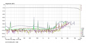
Thanks to this thread, I tried to do some loopback measurements of my USB audio interface, the Focusrite Scarlett 2i2. I used unbalanced cables for the loopback, and I believe this gives worse readings than balanced, but nevertheless, I wanted to see what I get. I also used Arta STEPS, not REW, because that's what I have.
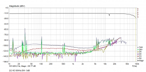
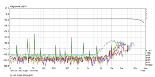
I set the sampling rate to 192K, and set the measurement bandwidth to 90KHz. I did three readings, once by setting the signal level at -3dB in the "Setup->Measurement" dialog box, once at -10dB, and once at -20dB. In each case, I tweaked the input level controls to get the input reading to come to about -10 to -12dB or so. So, though I was generating different levels of signals at the output, I was amplifying the inputs to compensate for these differences. I did this just to see what I get.
These are the three graphs I got.
Are these similar to what others are seeing?
Thanks to this thread, I tried to do some loopback measurements of my USB audio interface, the Focusrite Scarlett 2i2. I used unbalanced cables for the loopback, and I believe this gives worse readings than balanced, but nevertheless, I wanted to see what I get. I also used Arta STEPS, not REW, because that's what I have.
I set the sampling rate to 192K, and set the measurement bandwidth to 90KHz. I did three readings, once by setting the signal level at -3dB in the "Setup->Measurement" dialog box, once at -10dB, and once at -20dB. In each case, I tweaked the input level controls to get the input reading to come to about -10 to -12dB or so. So, though I was generating different levels of signals at the output, I was amplifying the inputs to compensate for these differences. I did this just to see what I get.
These are the three graphs I got.
Are these similar to what others are seeing?
- Why is there the big rise in HD at high frequencies? Is this normal even for signal level circuits? I know that it's common in power amps because the GNFB reduces at high frequencies.
- Why the sharp spikes in distortion at random frequencies? They are not repeatable -- they don't repeat at the same frequencies if I run the measurements again. And the laptop was battery powered during the entire session, disconnected from mains.
- Why is there the wide hump in the base level of THD across most of the frequency spectrum in the -3dB and -10dB readings, but not in the -20dB reading?
- Why are there those notches in the frequency response curve at the upper end of the spectrum? Those notches are repeatable.
Attachments
Can you please elaborate?Arta spectrum mode is your friend.
Maybe you should ask in an ARTA thread as I can’t help you here with REW. REW is free and awesome software. Also measures speakers and TS parameters. Multi purpose and very easy to use.
You also have John Mulcahy - the author ask questions he is a member in DIYA.
Looking at your loop back data I can only guess you are driving it too close to clip. Back off until about -20dB below when the red halo lights up on the gain knob.
Make sure your grounding is correct. Keep away from cell phones or noisy power equipment. Unplug your laptop from wall. Take data only in laptop battery powered mode.
Last edited:
Maybe you're right... The only way to get clear conclusions is to compare REW readings with the Arta ones I got. I will teach myself how to use REW. Is there anyone on this thread who's used REW on Linux? When I tried installing REW on my Ubuntu laptop, it couldn't even find my Java runtime in its auto-detect phase; I have JRE 11.4 installedMaybe you should ask in an ARTA thread as I can’t help you here with REW.
Wow. This is new learning for me. I'm definitely not doing that. What I was doing was setting the output levels to the three different settings I mentioned (-3dB, -10dB and -20dB) and then turn the input gain control till Arta's test mode VU meters showed me that signal strength was -10dB. I thought I was safe and far away from clipping if my input was -10dB.Looking at your loop back data I can only guess you are driving it too close to clip. Back off until about -20dB below when the red halo lights up on the gain knob.
I'll try red zone minus 20dB now.
Don't know what to do about grounding, but the other points were already being taken care of.Make sure your grounding is correct. Keep away from cell phones or noisy power equipment. Unplug your laptop from wall. Take data only in laptop battery powered mode.
Will do some fresh readings, with ARTA first and then with REW. Thanks a lot.
REW requires a Java 8 runtime.When I tried installing REW on my Ubuntu laptop, it couldn't even find my Java runtime in its auto-detect phase; I have JRE 11.4 installed
So it won't work with a later JRE version?REW requires a Java 8 runtime.
I am using REW in linux (Mint 19), works very good.
The startup script searches for available JDKs, looking for java 1.8. It is simple to add openjdk 8 to mint
The package is available in all ubuntus Ubuntu – Package Search Results -- openjdk-8-jdk
I just tested REW works perfectly with the latest Oracle JDK14, only the JAXB API removed from java > 8 need to be copied to the REW directory (jakarta.xml.bind-api-2.3.2.jar) + simple change in the startup script. I have not tested JDK builds from other providers, but IMO there is no reason to not work.
I am happy for that because newer JVMs implement many performance improvements and especially feature the new low-latency garbage collector ZGC - REW runs great with it enabled. I get almost no stream discontinuities in RTA at 96kHz samplerate.
John, thank you, fantastic work!
The startup script searches for available JDKs, looking for java 1.8. It is simple to add openjdk 8 to mint
Code:
sudo aptitude install openjdk-8-jdkThe package is available in all ubuntus Ubuntu – Package Search Results -- openjdk-8-jdk
I just tested REW works perfectly with the latest Oracle JDK14, only the JAXB API removed from java > 8 need to be copied to the REW directory (jakarta.xml.bind-api-2.3.2.jar) + simple change in the startup script. I have not tested JDK builds from other providers, but IMO there is no reason to not work.
I am happy for that because newer JVMs implement many performance improvements and especially feature the new low-latency garbage collector ZGC - REW runs great with it enabled. I get almost no stream discontinuities in RTA at 96kHz samplerate.
John, thank you, fantastic work!
Attachments

Question. If I am measuring a loopback distortion of 0.007% and I then hook up my amplifier and measure 0.015% what is the distortion of my amplifier?
This is great. I'll try installing REW again, with Java 14, and I'll copy over the missing module as you mentioned. Where can I find that module? Do I have to install JRE8 to get it or is it available separately?
In general I'd like to work with the latest stable releases of layered products. Never know what one loses if one uses an older release. The super-popular HolmImpulse uses some specific old version of dotNet; I decided not to use HolmImpulse.
In general I'd like to work with the latest stable releases of layered products. Never know what one loses if one uses an older release. The super-popular HolmImpulse uses some specific old version of dotNet; I decided not to use HolmImpulse.
The general impression I've been getting from discussions here is to take 0.015 - 0.007 = 0.008% as the distortion?Question. If I am measuring a loopback distortion of 0.007% and I then hook up my amplifier and measure 0.015% what is the distortion of my amplifier?
I believe some members are doing this per HD, not at the THD level, and then adding them up to get the derived THD.
I'm new to this; I too am learning.
tcpip: I have tested just the generator and RTA, not other parts. It was more of an info for John.
java8 is a very stable layer, many businesses are staying with it due to Oracle licensing changes and changes in Java9 breaking direct backward compatibility (hence the extra jars, e.g.). But java development goes on fast, of course (fortunately).
java8 is a very stable layer, many businesses are staying with it due to Oracle licensing changes and changes in Java9 breaking direct backward compatibility (hence the extra jars, e.g.). But java development goes on fast, of course (fortunately).
- Home
- Design & Build
- Software Tools
- How to - Distortion Measurements with REW