When I use my Behringer UM2 with a balanced line stage for an input, I tried the V+ to tip. V- to ring and ground to the sleeve. I ended up with massive amounts of harmonics, once I removed the ground from the sleeve, it worked perfectly. So now it is wired with the XLR to TRS with no ground, just V+ and V-.
I have noticed a similar thing - do not connect the GND pin when using balanced input. You are correct in wiring +ve to the tip and -ve to the ring. I may have said that backwards earlier in the thread.
I did mention previously in post 11 to leave the GND not connected.
Howto - Distortion Measurements with REW
I did mention previously in post 11 to leave the GND not connected.
Howto - Distortion Measurements with REW
Last edited:
When I use my Behringer UM2 with a balanced line stage for an input, I tried the V+ to tip. V- to ring and ground to the sleeve. I ended up with massive amounts of harmonics, once I removed the ground from the sleeve, it worked perfectly. So now it is wired with the XLR to TRS with no ground, just V+ and V-.
I remove gnd from the sleeve. Still horrible results here

I was thinking to use this
and then my xlr to rca adaptor.
but that would be the same as using one of these
Or do I just use one of these

I have a feeling all will have the same result.
An externally hosted image should be here but it was not working when we last tested it.
and then my xlr to rca adaptor.
An externally hosted image should be here but it was not working when we last tested it.
but that would be the same as using one of these
An externally hosted image should be here but it was not working when we last tested it.
Or do I just use one of these
I have a feeling all will have the same result.
Do you have a voltage divider on your input? Just make sure the maximum voltage does not exceed the max allowable input signal. That distortion is result of clipping at the input stage. What divider are you using at present ?
Use google to find "akitika voltage attenuator"
Document is a pdf. Build the switcable attenuator into a box
And add necessary connectors and labeling for straightforward use.
This is a cheap way to protect sound card input.
Document is a pdf. Build the switcable attenuator into a box
And add necessary connectors and labeling for straightforward use.
This is a cheap way to protect sound card input.
Does the XLR input allow line level signals?
I seem to recall that on another product, only the TRS was for Line and Guitar, and the XLR for Microphone only.
I seem to recall that on another product, only the TRS was for Line and Guitar, and the XLR for Microphone only.
Do you have a voltage divider on your input? Just make sure the maximum voltage does not exceed the max allowable input signal. That distortion is result of clipping at the input stage. What divider are you using at present ?
Yes. I use a 20k/2k divider. This produces 1.2v at the input to the TRS. This is quite adequate as it can allow for 7.5v max when using the trs input.
@niss_man
Where do you get the test signal from? Separate generator, or DUT looped between soundcard out / soundcard in (Soundcard being the Behringer or separate between In- and Output)?
Where do you get the test signal from? Separate generator, or DUT looped between soundcard out / soundcard in (Soundcard being the Behringer or separate between In- and Output)?
Separate signal gen.Here is a measurement using my Behringer 202HD and the LT AN67 signal generator as shown on these threads. EOSC10Kv3 - LT AN67 10kHz oscillator : new updated version !
View attachment 768550
Separate signal gen.
Thanks. But this attachment shows a decent result, so what is different now?
Balancing an Unbal signal with a preamp to feed the Behringer?
Hi Folks,
Member Vicnic has developed a very nice -150dB to -160dB THD 1kHz oscillator. You can contact him via PM if interested. I am going to get one - although the instrumentation end (Focusrite) will not be capable of resolving the distortion without a notch filter and more time averaging. They are 45 Euro built and tested.


Member Vicnic has developed a very nice -150dB to -160dB THD 1kHz oscillator. You can contact him via PM if interested. I am going to get one - although the instrumentation end (Focusrite) will not be capable of resolving the distortion without a notch filter and more time averaging. They are 45 Euro built and tested.
Nice work Nissman! Looks like you have figured it out and use of separate signal generator was key.

How will you get a distortion-free very-high-Q notch filter? I guess it will have to be passive, right, to keep distortion low? Are there circuits/kits available for these?Hi Folks,
Member Vicnic has developed a very nice -150dB to -160dB THD 1kHz oscillator. You can contact him via PM if interested. I am going to get one - although the instrumentation end (Focusrite) will not be capable of resolving the distortion without a notch filter and more time averaging. They are 45 Euro built and tested.
Try this one. I still have to build the board.
PCB for Samuel Groner's low distortion passive notch filter
PCB for Samuel Groner's low distortion passive notch filter
Wow. What awesomeness. Will ask if more PCBs are available. And ouch! SMD! 🙁Try this one. I still have to build the board.
PCB for Samuel Groner's low distortion passive notch filter
I just measured the distortion in my first Class D amp with REW and this setup. No low-pass filter. Using a 11:1 attenuator with 2k2 and 22k resistors on a small veroboard. I took a 6m XLR male-female cable and cut it in half and used the male end soldered to the veroboard.
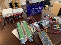
Here is a photo of the dummy resistor rig (2x 100w 8ohm resistors for 100w 8ohms or 200w 4ohm load, voltage divider, and female spade connectors for connecting to amp under test, and XLR cable to got to measurement sound card:

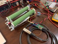
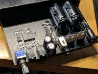
Here is photo of setup underway, I originally thought I needed a wall powered headphone amp for a preamp, but found that the Akitika had no problem driving the 3E amp to clipping since gain is set at 27dB, Without the Schiit M3 preamp, there was no mains 60Hz or harmonics:

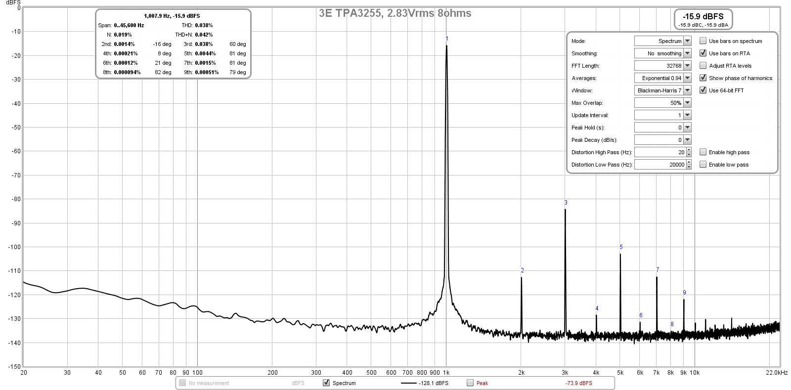
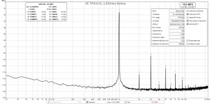
Here is FFT for 2.83vrms into 8ohms (1w):
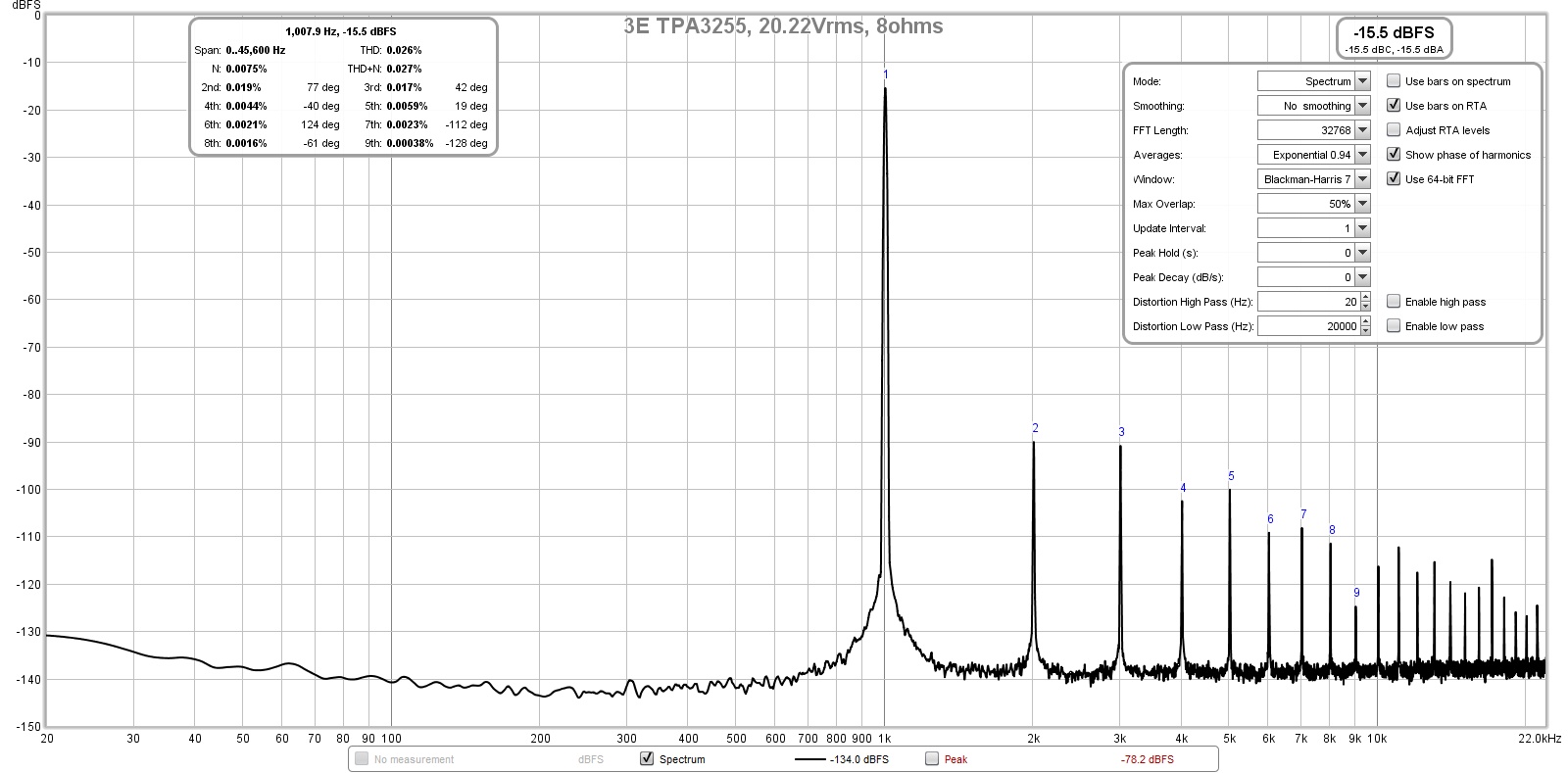
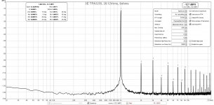
Here is FFT for 20vrms into 8ohms (50w):
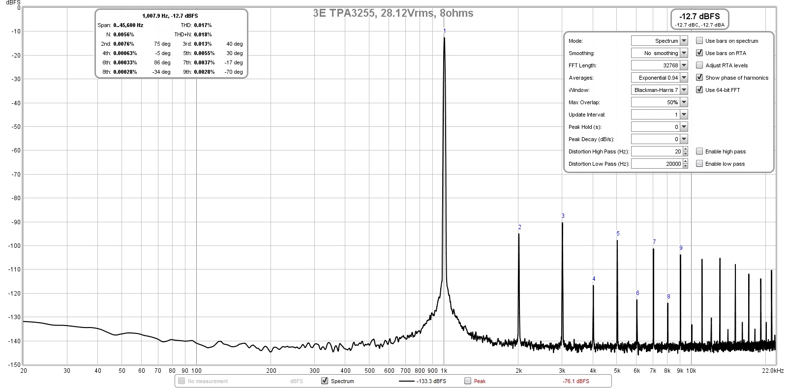
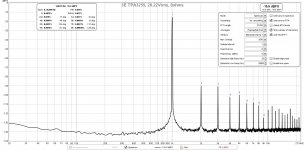
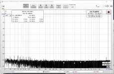
Here is FFT for 28.3vrms into 8ohms (100w)
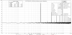
Here is FFT for 34.6vrms into 8ohms (150w) and onset of clipping (note how noise floor rose up):
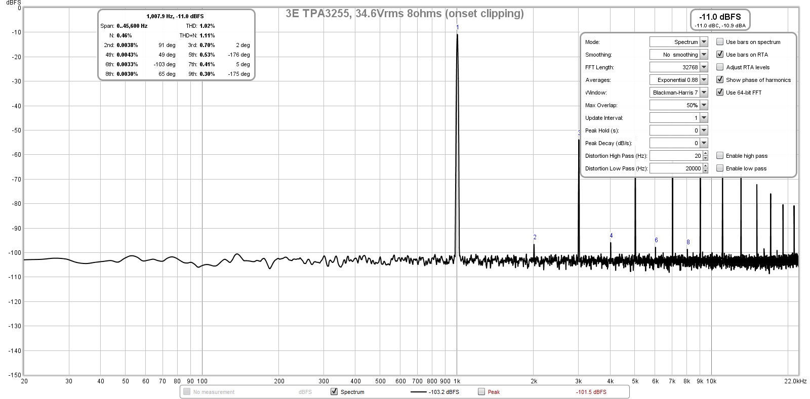
The TPA3255 is powered by a 1200w DC-DC step up from a 12v 35Ahr lead acid gel cell battery. Note the total absence of mains line hum or harmonics. It is very quiet this way.
Here is a photo of the dummy resistor rig (2x 100w 8ohm resistors for 100w 8ohms or 200w 4ohm load, voltage divider, and female spade connectors for connecting to amp under test, and XLR cable to got to measurement sound card:
Here is photo of setup underway, I originally thought I needed a wall powered headphone amp for a preamp, but found that the Akitika had no problem driving the 3E amp to clipping since gain is set at 27dB, Without the Schiit M3 preamp, there was no mains 60Hz or harmonics:
Here is FFT for 2.83vrms into 8ohms (1w):
Here is FFT for 20vrms into 8ohms (50w):
Here is FFT for 28.3vrms into 8ohms (100w)
Here is FFT for 34.6vrms into 8ohms (150w) and onset of clipping (note how noise floor rose up):
The TPA3255 is powered by a 1200w DC-DC step up from a 12v 35Ahr lead acid gel cell battery. Note the total absence of mains line hum or harmonics. It is very quiet this way.
Attachments
-
 3E-TPA3255-34.6vrms-8ohms-FFT-onset-clipping.jpg237 KB · Views: 1,316
 -
 3E-TPA3255-28.13vrms-8ohms-FFT.jpg236.8 KB · Views: 3,072
 -
 3E-TPA3255-20.22vrms-8ohms-FFT.jpg235 KB · Views: 2,647
 -
 3E-TPA3255-2.83vrms-8ohms-FFT.jpg230.8 KB · Views: 1,318
 -
 TPA3255-test-Setup.jpg943.9 KB · Views: 3,018
 -
 Dummy-load-rig.jpg447.4 KB · Views: 1,303
I just stumbled across this chap (quite possibly a member here?) who, inspired by this very thread, decided to dip his toes into the treacherous waters of DIY loopback measurements:
https://enjon.uk/2019/09/01/a-diy-approach-to-distortion-measurements-for-audio-amplifiers/
I thought it would make an interesting illustration of the pitfalls to be encountered by those unfamiliar with the terrain.
1. He decided to use an existing Behringer UCA202 - which unlike the Focusrite used by xrk971 only features an unbalanced input.
Do I hear somebody say Uh-Oh there? That's right, it's ground loop time. The signal is sent round in a loop, and so is the ground. See the mains harmonics at -70..-80 dBFS in his graphs? Dead giveaway.
So how do we fix this? Should be easy enough here - inside the attenuator box, replace the black wire going to output RCA ground by a resistor of somewhere around 1 kOhm (value not critical).
A balanced input would have provided some common-mode rejection, but here there is none.
2. Maximum input level on the UCA202 is ca. 1.25 Vrms. Together with a ca. 12.7 kOhm input impedance, the 22k/2.2k voltage divider just barely covers the nominal 25 Wpc (14.14 Vrms) of the Cambridge Audio A1 used for testing, but would have to be changed for anything beyond 30 Wpc.
3. The Aneng AN8008 used for level calibration is a TrueRMS multimeter with a -3 dB bandwidth of ca. 3 kHz. Assuming that's a 1st order response, this would mean that amplitude reading on a 1 kHz signal would be about 5% or 0.46 dB out. Nothing major, but the displayed 2.830 V may actually be closer to 2.983 V. Cross-checking with a lower frequency like 100 Hz and computing a suitable correction factor may be advisable.
4. The UCA202 ADC actually isn't that much to write home about, with a fair amount of periodic ripple gracing its frequency response and and dynamic range in the 80s of dB. Better than nothing but not exactly "measurement grade".
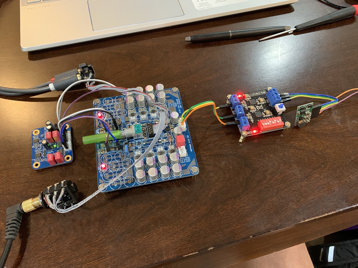
8x OPA1622 Headphone amp powered with eBay TPS7Axxx dual rail +/-18v PSU and +/-24v DC-DC step up from 12v battery.
For 1.0Vpp into 8ohms, getting clean -130dB noise floor and 5.7ppm THD with mostly H2 and H3.
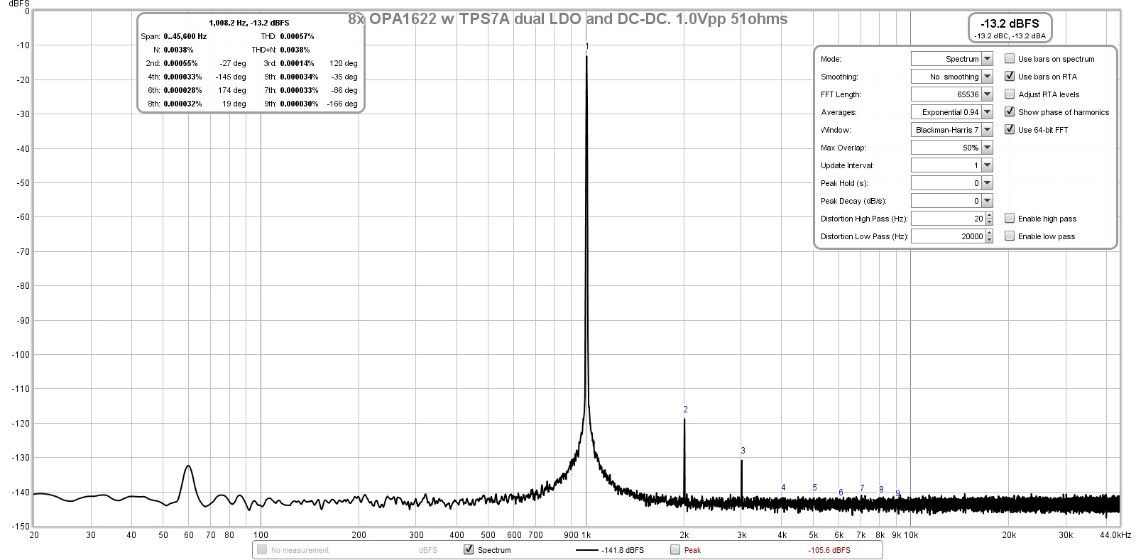
For 1.0Vpp into 8ohms, getting clean -130dB noise floor and 5.7ppm THD with mostly H2 and H3.

- Home
- Design & Build
- Software Tools
- How to - Distortion Measurements with REW