Self and Cordell have both written very good books on amplifier design.
It is to recommend for building good amplifiers.
It is to recommend for building good amplifiers.
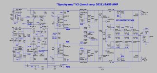
Built this for a friend in 2014 , it still works today with a dayton 12" sub.
Another friend uses a similar circuit to run VERY power hungry 15-18" subs. 2014 - present. - he uses 7 pair sanken MT-200's !! Yikes !
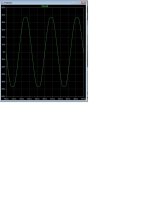
It has very good PSRR and the hawksford VAS can clip without many upper harmonics. A nice "rounded"
symmetrical overload waveform. VAS red led's light up in overload.
go ahead and feed 2V at the input .... tubelike. Output devices never saturate. Bombproof ultima !
PS - for sub/bass use , one could leave out the cap multipliers and just use a simple zener 24V regulator without the series pass devices.
Symmetrical designs natively cancel rail ripple , hence why this circuit is ideal for a dedicated bass amp. Smaller 4700-6800uF filter caps
will be plenty for even 300W usage. Also, mine ran cool with 30ma/ device (6mV) bias. Xover distortion components are nowhere near a
woofers audible range.
Another friend uses a similar circuit to run VERY power hungry 15-18" subs. 2014 - present. - he uses 7 pair sanken MT-200's !! Yikes !
It has very good PSRR and the hawksford VAS can clip without many upper harmonics. A nice "rounded"
symmetrical overload waveform. VAS red led's light up in overload.
go ahead and feed 2V at the input .... tubelike. Output devices never saturate. Bombproof ultima !
PS - for sub/bass use , one could leave out the cap multipliers and just use a simple zener 24V regulator without the series pass devices.
Symmetrical designs natively cancel rail ripple , hence why this circuit is ideal for a dedicated bass amp. Smaller 4700-6800uF filter caps
will be plenty for even 300W usage. Also, mine ran cool with 30ma/ device (6mV) bias. Xover distortion components are nowhere near a
woofers audible range.
Attachments
Last edited:

Hard to find many online images of this as a replacement driver. They never blow with Polk's junk amps. Magnet is as big as my 10" sub !Ostripper,
Could you show a picture of the Polk XT 12 bass driver?
Attachments

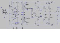
Here is an even easier one. Most likely it will be this ....
-simple EF2 (Badger output stage)
-50V rails. Most OEM's are similar.
-Just 4700uF rail caps , symmetrical designs are native "ripple eaters".
-Hawksford red led VAS can clip all day (below 2). .... at 92V p-p.
- .01% is fine for a sub amp. 2 pair TO-3P at <50V can drive 200W/4R.
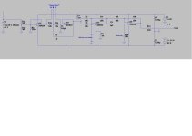
I will also make a combined Filter with phase and a remote start board to go with it.
It will replace any of the parts express junk ( or the absolute OEM junk). Just
add a 200VA 35-0-35 toroid.
-simple EF2 (Badger output stage)
-50V rails. Most OEM's are similar.
-Just 4700uF rail caps , symmetrical designs are native "ripple eaters".
-Hawksford red led VAS can clip all day (below 2). .... at 92V p-p.
- .01% is fine for a sub amp. 2 pair TO-3P at <50V can drive 200W/4R.
I will also make a combined Filter with phase and a remote start board to go with it.
It will replace any of the parts express junk ( or the absolute OEM junk). Just
add a 200VA 35-0-35 toroid.
Attachments
You must select them for voltage and use four pairs. You then have to ask yourself if you are any better off. More transistors, more emitter resistors, more mounting hardware and a bigger PCB.
With free/paid for transistors the equation is a little more favorable, but if you’re low on TO-247 insulators or don’t have room for more emitter resistors, or have to buy all the extra parts it becomes less favorable.
With free/paid for transistors the equation is a little more favorable, but if you’re low on TO-247 insulators or don’t have room for more emitter resistors, or have to buy all the extra parts it becomes less favorable.
Yes , anything could be used. Those tips are "slow" ... but this is a sub amp. I "crippled" the HF , anyways. As a full range amp , 22-33pF miller caps wouldHello Ostripper,
Could ultra cheap output devices such as TIP2955/3055 also be used?
even make a nice stereo amp with this design.
- Home
- Amplifiers
- Solid State
- How to design and build a dedicated Bass Power Amplifier. Is it different?