The idea of a "rubber throat" goes beyond the discussion in that short illustrative article, which I linked (and you said that you were not familiar with the basic concept, above), a concept apparently first described by Olson, 1938.
Rather you seem to stuck on the idea that "constant flare rate" as a horn/driver design criterion is worthy of its own merit without consideration of other design factors and resulting performance issues.
The more general idea of designing to a changing "flare rate"...actually this term only works if we're talking exponential expansions....in the early stages of horn expansion--or even in the later stages--is that it is a design criterion that can (and really must) change in order to achieve more than just the avoidance of impedance bounces and highest efficiency/acoustic resistance curves throughout the horn expansion. There are other design factors to consider, and you've not mentioned those factors.
I invite you to hear a K-402 horn with virtually any full-range compression driver. Then look carefully at the horn area expansion rate curve, including the expansion starting within the compression driver, transitioning to the horn entry.
What you think that you know...you may not really know.
Chris
You've never seen a multiple entry design based on a straight-sided pyramidal horn?
Sure, the midbass horn I use is bifurcated (not straight sided but hypex) and it sounds great. I don't think that defines a true rubber throat because it's first section has a slower flare than the mouth section. Isn't the rubber throat the opposite of that? My Keele HR6040 / 9040 horns might fit that fast first, slow flare mouth better. I never looked at them that close.
http://www.audioartistry.com/patents.htm
Last edited:
Like this?
doityourselfaudio: 140Hz Petal Horns
I had the impression your preference was for cone-loaded horns in this range.
Still, I'd quite like to hear it for myself, a compression driver on a really big horn.
Yes, I prefer a cone below around the 600-800 cycle point - depends on a lot - mainly the quality of the midrange of the bass horn. smaller drivers like 8-10" seem to be the sweet spot.
Big compression driver horns can be fun. I have a few of them here 🙂
The idea of a "rubber throat" goes beyond the discussion in that short illustrative article, which I linked [...]
I invite you to hear a K-402 horn with virtually any full-range compression driver. Then look carefully at the horn area expansion rate curve, including the expansion starting within the compression driver, transitioning to the horn entry.
What you think that you know...you may not really know.
Chris
I'd like to hear a K-402 (or a home-made equivalent).
I don't follow what your reasoning, though. The article was illustrated with a stepped-on exponential horn that had lots of abrupt changes. The K-402 looks like their version of the Geddes concept: conical with smooth roundovers. How are these alike?
Rather you seem to stuck on the idea that "constant flare rate" as a horn/driver design criterion is worthy of its own merit without consideration of other design factors and resulting performance issues.
? confused: this looks like it was addressed to me, but I've mentioned other design factors (e.g. pattern control) earlier in this thread, so it doesn't seem to fit.
The point that I was driving at was that "rubber throats" or changing area expansion rates (like the generalized subject that Olson presents) in compression drivers and their attached horns are influencing much more than just minimization of impedance bounces and horn/driver efficiencies. Avoidance of distortion due to thermodynamic properties of air/water in the throat high intensity areas, avoidance of HOM propagation down the multiple horn "mouths", or backwards into the phase plug/diaphragm assembly, causing complex back-acoustics-induced distortions, controlling the frequencies of the impedance bounces to above or below the most sensitive frequency bands for human hearing, and also avoiding the effects of more rapid area expansion in the compression driver exits to their overall efficiency and effective lower bandwidths.
All of these factors are wrapped up with compression driver area expansion rate differences along their axial length, and the desirability of changing the throat area-expansion rate to minimize the other areas of driver/horn performance. It's not a more simplistic scenario, unfortunately.
One of the learning opportunities that I came across a few years ago was in watching the attempted redesign of the TAD TD-4002 long snout to make it shorter and the area expand faster. This was driven by the perceived notion that the existing snout was in some way "bad". After many months, many redesign iterations and test articles, it was decided that the original snout (with slow area expansion rate) wasn't so bad after all. The issues that arose in trying to modify this one piece of metal with a hole in it in order for it to perform "better" were all over the map in terms of all the bad side effects that occurred. I think that the exercise got the whites of everyone's eyes.
The notion that this area of design is "good" or "bad" just looking at a piece, or picking some random dimensional or rate-related factor, was clearly an exercise in learning about the dynamics of highly coupled complex system design--in ways that no one imagined at the outset.
Chris
The slow flare in the old drivers work with the big horns that sound good with the slow flare and mated with a bass horn. They can also be good with mid size 300 hz horns. The short fast flare drivers (radian, celestion, new JBL mid format, Faital ect) are for the fast flare new style horns that are mostly used much higher with success and mated with the compromised direct radiation low range. It has zero to do with fidelity IMO and has to do with size and weight compromises.

Sorry for bringing this thread back from the dead, but I figured I'd add to existing knowledge rather than distributing it in to another thread. 😉
I'm designing my first set of speakers and decided to go with a 15" woofer / compression driver 2-way combination. I got a great deal on a pair of FaitalPro HF201s and I'm trying to choose an appropriate horn for them. My intent is to cross them over at 1khz. This is for home hifi use.
It seems as though there are not as many choices for a 2" throat compression driver as there are smaller throat sizes. I have looked at some of the options described previously in this thread. The Eminence H2EA seems like my best option, given its feedback. There is also the Goldwood GM450PB which seems to be a JBL replica. I also found the P-audio PH2380 which seems to be an older JBL design copy. I'm sure there are others as well. I figured some things likely have changed since the last update to this thread in 2016 and it was worth another ask. Any suggestions?
A 15" on a baffle is ~90 deg/1.2 kHz and ~60 deg/1.6 kHz and the 201 is nominally a 500 Hz driver, so the GM450PB is a better choice, though the 2380 should hold the pattern lower, so absent polar response/DI plots it would be my choice of the bunch plus short of one needing 100 W/1 kHz power handling can be XO'd lower, so recommend trying 7-800 Hz to shorten the C-T-C acoustic spacing.
GM
GM
It seems as though there are not as many choices for a 2" throat compression driver as there are smaller throat sizes. [...] I figured some things likely have changed since the last update to this thread in 2016 and it was worth another ask. Any suggestions?
Seller zxpc on ebay has a few options e.g.
(A)
2" Throat Horn Bolt-On 18"x10"For Assorted Bolt On 2"Exit Drivers 90degx 40deg(398) | eBay
(B)
11" x 17" ABS 2" Bolt-On Long Throw Horn 90deg x 40deg For Many 2" Exit Driver 647356202421 | eBay
I used the latter horn (B) in this project:
Fairly big horn for 2" drivers - Album on Imgur
This is still in use, running >700Hz with a small 'full range' driver.
...though the 2380 should hold the pattern lower, so absent polar response/DI plots it would be my choice of the bunch plus short of one needing 100 W/1 kHz power handling can be XO'd lower, so recommend trying 7-800 Hz to shorten the C-T-C acoustic spacing.
GM
Thanks for the feedback. When you say "hold the pattern lower," does this mean that there will be less vertical dispersion?
I've been trying to understand the "why" of choosing a horn and I can't say that any of this reading has helped me understand why choosing one horn over the next would be better from a sound perspective. This article has been really interesting to read and try to understand. I guess I expected the concept of selecting a horn to be as much about the effect on frequency response of the driver as directing the sound where you want it efficiently.
@hollowboy thanks for the links! Both of those are a bit larger than I was looking for, but I will check out what else the seller has to offer. Unfortunately, my listening room is pretty small, so I can only get away with about an 18" wide cabinet, but that is really pushing things, as it would cause the door to the room to not open completely. First world problems, I know. 🙁
“Holding the pattern lower” means able to maintain a sound radiation characteristic to a lower frequency . For example, a typical symmetrical 90° by 60° horn will be 6dB down 45° off axis in one orientation and 6dB down 30° off the axis perpendicular to that. Horns that have circular mouths are axisymmetrical and thusly have only one radiation angle. The wider the physical dimensions of the horn at the mouth, the lower in frequency it can maintain that pattern. The aforementioned 90° x 60° horn would typically be oriented so that the 90° of radiation was in the horizontal plane and the 60° was in the vertical plane.
Speaker building is unfortunately one of those hobbies where it’s hard to know what questions to ask because if you knew which questions to ask you wouldn’t need to ask them in the first place. The “unknown unknowns” as Rumsfeld put it.
Usually people have enough contraints that their selection process is narrowed from the outset. In your case, the contraints seem comparatively minimal.
What is your listening distance from the loudspeakers you have in mind, also, how far from your listening position are the sidewalls (incl ceiling) of your room?
Thanks for the reply. Makes sense. This whole exercise is to get full range in a high sensitivity package for flea power. I have a pair of 300B based amplifiers that I really like and the DIY route seemed the best option for me. I prefer the <200hz "punch" of a larger driver, so I ruled out transmission line with a full range driver, in case you're wondering (admittedly, some of this is prejudice, but I'm also factoring in my building skill ability and availability of tools.) I have the HF201's in hand, as well, so I'm pretty committed. The woofer that I intend to use is the Faital Pro 15PR400. Both of these drivers appear to have "tube friendly" impedance curves and good frequency response is how I arrived at these choices. I'm targeting approximately 150 liter volume cabinets, with my major constraint being the width. I need to make the cabinet width as narrow as possible.
My listening room is sub-optimal, for sure. It's a spare bedroom that primarily serves as a music room, but can also sleep dinner guests that were a bit too indulgent. Here's a sketch of the room and the distances. It's pretty small, oddly shaped and has power location limitations causing this configuration to be the overall best choice. One thing not on the diagram is that there is a window above the cabinet on the right side. Thanks again for your advice!

My listening room is sub-optimal, for sure. It's a spare bedroom that primarily serves as a music room, but can also sleep dinner guests that were a bit too indulgent. Here's a sketch of the room and the distances. It's pretty small, oddly shaped and has power location limitations causing this configuration to be the overall best choice. One thing not on the diagram is that there is a window above the cabinet on the right side. Thanks again for your advice!
Well, one trade-off with a 2” compression driver such as you’re using is beaming that starts just below 7000Hz and continues upward. I have no idea how good your hearing is (this may be inaudible to your ears due to work- or age-related hearing loss) so this may be of little consequence.
Another thing to keep in mind is the posted impedance and frequency response graphs for the compression driver you purchased are only telling you how it measures when used with the horn that was mounted to it for testing. Use a different horn and the results will vary.
Another way to approach this is to work backwards from the maximum allowable width of your cabinet, also keeping in mind whether or not you intend to roundover the edges of your baffle to reduce diffraction. Decide wether or not you are going to have your horn mounted in the baffle or, as some folks do with fiberglass horns (Le Cléac'h), on top of the cabinet. If you’re mounting it within the enclosure, your maximum allowable baffle width is going to determine the maximum width of the horns you can consider. You may find that the only horns you can consider are unable to take advantage of the low frequency crossover point your compression driver is capable of.
The closer the loudspeakers are is to the wall behind them, the less baffle step compensation is theoretically required of the crossover.
If you can place a futon mattress on the floor between the loudspeakers and the listening seat, this will reduce destructive interference due to floor bounce. The alternative is an active midbass module low passed around 200-250Hz. With midbass modules used as “stands” for your main speakers, you could run your woofers in a sealed enclosure and possibly avoid baffle step compensation altogether, which would better meet your criteria for maximum use of available watts.
I guess I expected the concept of selecting a horn to be as much about the effect on frequency response of the driver as directing the sound where you want it efficiently.
It is - the two are linked.
(A) Horns that have a wide, even pattern (consistent sound across the area covered) have drooping HF. They need more EQ to get flat response.
(B) Horns that have a sweet spot 'beam' the HF. They need less equalisation for that spot ...but they have less HF everywhere else.
Broadly speaking, in the past, measurement and EQ were harder to do, so (B) was easier to get right. It is still a good choice in some circumstances.
Because measuring and signal processing gear has become hella cheap, (A) is becoming more common.
@hollowboy thanks for the links! Both of those are a bit larger than I was looking for, but I will check out what else the seller has to offer.
They do have some that are more compact.
You can also hack a too-big horn. Take an 18" wide horn, grind the flange off, and you'll get a ~15" wide horn. ABS plastic can be cut and worked pretty easily. You'd lose 4 mounting holes, but could make up for that loss of strength by bracing the 'neck' of the horn.
Another type I've considered are "audiopipe" and similar (car sound) horns, e.g.
Audiopipe 7.75" Octagon High Frequency Aluminum Horn for 2" Bolt On Exit Drivers 647356206511 | eBay
I like the shape, hate the bling. If I bought them, I'd:
grind off the shiny bits
repaint in basic black
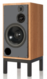
rear mount (to a chamfered cutout) so it looked something like the attached image
That's an ATC speaker. The rear mounted midrange horn looks good, IMO.
Unfortunately, my listening room is pretty small, so I can only get away with about an 18" wide cabinet, but that is really pushing things, as it would cause the door to the room to not open completely. First world problems, I know. 🙁
Can you free up floor space by going vertical - e.g. suspend big 2-ways from the roof?
Attachments
Another thing to keep in mind is the posted impedance and frequency response graphs for the compression driver you purchased are only telling you how it measures when used with the horn that was mounted to it for testing. Use a different horn and the results will vary.
Interesting point. I hadn't considered the impact of the horn on impedance, and I assume, phase angle as well. Is there a way to predict the impact that a horn (or other factors) will have on impedance and phase angle? I was hoping to keep the experimentation to a minimum. 😉
@hollowboy thanks for the link on the Audiopipe horn. Agreed on the bling. They do seem to have more than one size available, but absolutely no performance details.
I like the idea of having the horn be external. That will allow me to experiment with different horns without having to chop off the baffle. I may go this route.
Assuming you bought the compression driver because you like it’s measured performance, your safest bet is to find out what horn it was measured with and buy that. Did you buy your compression drivers new or used?
Experimenting with different horns could be fun but you will likely discover some plastic horns rely on being rigidly mounted to a baffle to suppress resonances in the horn itself. The fiberglass horns from autotech and wooden horns are the only type I’ve seen set atop a loudspeaker enclosure.
Food for thought: if the top of your loudspeaker is flat, you can set the amplifier on it. This alternative may reduce the size of the equipment rack you plan on placing between your speakers, perhaps freeing up space to make your enclosures wider. There are some highly efficient 18” woofers. Also, there’s some really great sounding, high sensitivity dual woofer designs such as the 88 Special from diysoundgroup (designed by Jeff Bagby). I currently run one as my center channel but I’ve also built a pair and used them in a stereo setup and preferred them to the Fusion 12 (which I’ve also built a couple pairs of).
They do seem to have more than one size available, but absolutely no performance details.
Exponential horns of similar dimensions should all be more or less alike. That is: if multiple manufacturers each make an exponential horn of the same length and mouth area, their LF cutoff points will all be the same.
The only differences will be in coverage angles, which, in the absence of a spec sheet, can be guesstimated.
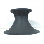
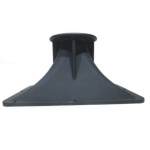
e.g. the attached pics show that audiopipe horn flanked by the profile images of the H2EA (nominally 60x40 coverage, 700Hz cutoff). The audiopipe has a profile about halfway between those angles.
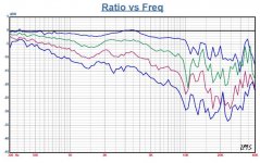
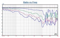
Also attached: normalized and off axis FR plots for H2EA, from Test Bench: Eminence N314T-8 with H14EA Horn and N320T-8 with H2EA Horn | audioXpress
I like the idea of having the horn be external. That will allow me to experiment with different horns without having to chop off the baffle. I may go this route.
Another way is to make a section of the baffle swappable, similar to this:
Rutcho's Universal Backloaded horn for different 8-inch fullrange drivers
The exposed, hot rod-aesthetic of having a freestanding horn is cool, but IMO suits big rooms that can showcase a big, flashy pile of gear.
In a small room, I think there's more benefit to having the horn set into the main box:
a) the air volume behind the horn is used by the woofer, not wasted
b) as Brinkman says, the top of a regularly shaped cabinet = an extra place to put things
Attachments

Last edited:
If you are just getting into horns for a home speaker, build an Econowave. 1" compression driver on a horn, 12" woofer. Chances are you will be satisfied for quite a while. In my opinion it's the best bang for the buck in DIY. Also, you can make angled cabinets and fit them into the corners of your room to save space and get excellent pattern control plus a bass boost. All this is much easier with active amplification and DSP - a Hypex Fusion plate amp will complete the system and hide inside the cabinets.
I made a pair using the parts below (the horn is a clone of the QSC waveguide - sounds fantastic and costs $11)
B-52 PHRN-1014 1" Horn 10" x 14" Bolt-On
Dayton Audio D250P-8 1" Polyimide Compression Horn Driver
Dayton Audio PA310-8 12" Pro Woofer
I made a pair using the parts below (the horn is a clone of the QSC waveguide - sounds fantastic and costs $11)
B-52 PHRN-1014 1" Horn 10" x 14" Bolt-On
Dayton Audio D250P-8 1" Polyimide Compression Horn Driver
Dayton Audio PA310-8 12" Pro Woofer
1" compression driver [...] you can make angled cabinets and fit them into the corners [...] active amplification and DSP - a Hypex Fusion plate amp will complete the system and hide inside the cabinets.
These look like fine ideas, but maybe not for this guy - I think you missed post 53 🙂
- Status
- Not open for further replies.
- Home
- Loudspeakers
- Multi-Way
- How to choose a horn/waveguide for home audio?