

What'e the resistance between gate and source for the output FETs with and without the driver board?
I'm assuming that one driver board is still out of the main board.
What'e the make/model of this amp? I have photos of a similar amp but don't remember what it was.
I'm assuming that one driver board is still out of the main board.
What'e the make/model of this amp? I have photos of a similar amp but don't remember what it was.
The reason that the amp likely went into protection without the driver boards was because one or more FET had a charged gate. The only pulldown resistors are likely on the driver board (R29A and R30A).
Will the amp try to power up if you insert a current limiter in the B+ line?
Will the amp try to power up if you insert a current limiter in the B+ line?
No, the amp draws excessive current all the time.
My bench supply could be adjusted up to 15Amps.it doesn't work, because it never go over 9.7V input. If I remove the rectifiers, it pulls only 1.6Amps.
With rectifier installed, but without drive boards inside, it directly goes into protection. The same, when the output mosfets are removed..
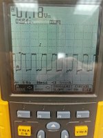
It seems to me, that the audio part is starting at the same time as the power supply, and that pulls to much current at a time. So the square wave can not build well.
My bench supply could be adjusted up to 15Amps.it doesn't work, because it never go over 9.7V input. If I remove the rectifiers, it pulls only 1.6Amps.
With rectifier installed, but without drive boards inside, it directly goes into protection. The same, when the output mosfets are removed..
It seems to me, that the audio part is starting at the same time as the power supply, and that pulls to much current at a time. So the square wave can not build well.
With your meter connected across those points, twist the transformer to see if the reading changes significantly.
No, it doesn't make any difference.. I checked the auxiliary voltages again, also OK.. + - 12V, 9Vat the drive board...
Some of these amps do require a LOT of current to start.
If you solder a bridge between the G and S of M1A and M2A on the driver board (with all components in the circuit), does the amp power up?
If you solder a bridge between the G and S of M1A and M2A on the driver board (with all components in the circuit), does the amp power up?
With the bridge inside, it power up. But I have no square wave at the gate of the audio output fets.
I don't think this is a problem but check the frequency of the PS drive. If it's too high, it can make the supply struggle.
Enable one board at a time by desoldering the bridges (hopefully the bridge is on the top side).
Will it power up like that?
If it still won't, pulse the remote repeatedly to see if you can incrementally charge the rail caps. Will it power up and produce drive to the outputs if the caps are charged.
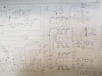
I think 47 ohms is too high to be in series with the driver IC. The 4.7 ohm is likely the right value.
You can edit/markup PDF files in the PDF reader. There is no need to photograph/scan it. IT's not important here but it may be for files you want to save.
You can edit/markup PDF files in the PDF reader. There is no need to photograph/scan it. IT's not important here but it may be for files you want to save.
I changed the resistor to 4.7 ohm. As soon as I connect remote, the resistor starts burning...
Thanks for the info with the PDF reader.. I will check it out.
Thanks for the info with the PDF reader.. I will check it out.
- Home
- General Interest
- Car Audio
- How to check dlogixs dp 4500 drive boards?