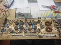
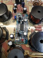
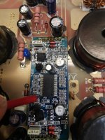
I received this amp, with a burnt ps.. Amp draws excessive current. Mosfets are all OK, railcaps also OK. If I remove the rectifier, idle current is OK. Removed drive boards, but the amp directly goes in protect.

On the 6-pin connector of the PS driver board, are the pins, L-R:
Ground
Ground
Remote
B+
Drive
Drive
Ground
Ground
Remote
B+
Drive
Drive
OK, if I remove the lm 7812 or 7912 the amp current ist normal. I expect a damaged dlogix ic.. How can I measure them?
Can't check the drive signal, when the amp is draw so much current.. If I remove the voltage regulators, the driver is dead...
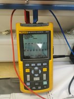
The PS is working well... I need to test the Audio Part
The PS is working well... I need to test the Audio Part
What's preventing you from checking those terminals when the regulators are out?
You could even check them with no power applied.
I'm looking for some sort of reference and I need to know what this driver board is. The pins will give me a better chance of finding a match. Otherwise, I'm going to have to work blind or let someone else help.
You could even check them with no power applied.
I'm looking for some sort of reference and I need to know what this driver board is. The pins will give me a better chance of finding a match. Otherwise, I'm going to have to work blind or let someone else help.
Started from left.
Ground
Ground
Rem
Bat
Drv
Drv
I have only 4 fets inside PS, also other part number for testing.
Input voltage is 12.2v
Ground
Ground
Rem
Bat
Drv
Drv
I have only 4 fets inside PS, also other part number for testing.
Input voltage is 12.2v
Attachments
Remove the rectifiers.
For the other pins on that board, post the DC voltage when the amp is in protect.
For the other pins on that board, post the DC voltage when the amp is in protect.
The amp not going into protect, only if i remove the output drive boards, or the output fets.
I will put the regulators back, remove the main rectifiers and check the Voltages.
I will put the regulators back, remove the main rectifiers and check the Voltages.
Put everything back in place,
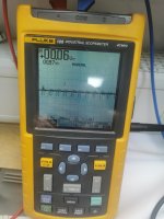
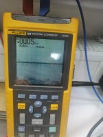
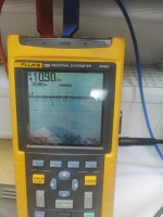
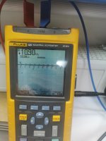
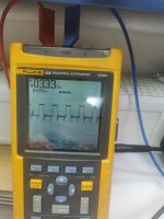
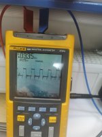
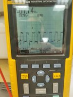
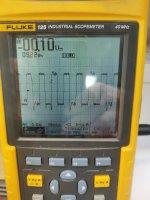
And opened the driver fets on the drive board to check the signal. Highside looks OK, but lowside not. If I put the fets in place, the signal is no square wave anymore. Could this belong to a dead drive ic, or undervoltage?
And opened the driver fets on the drive board to check the signal. Highside looks OK, but lowside not. If I put the fets in place, the signal is no square wave anymore. Could this belong to a dead drive ic, or undervoltage?
Attachments

The IC has one output that's split to high and low drive in the drive circuit.
What points were you probing for the images?
Is there any DC offset on the drains of the outputs?
Are the rectifiers in the circuit?
Are the FETs in the circuit?
What points were you probing for the images?
Is there any DC offset on the drains of the outputs?
Are the rectifiers in the circuit?
Are the FETs in the circuit?
Have you confirmed that all of the voltages marked on the header pins are correct?
Are you sure that there is no drive on pin 6 of the 4060?
Are you sure that there is no drive on pin 6 of the 4060?
Use a ground that's on the driver board and ground the scope to that to see if the signal looks cleaner.
Be careful not to short to a supply pin when connecting the ground.
Be careful not to short to a supply pin when connecting the ground.
- Home
- General Interest
- Car Audio
- How to check dlogixs dp 4500 drive boards?