Hi everyone,
as the title suggests, i would like to build a simple, low power guitar amp. I have been thinking this for a long time, but my interest became a desire when i saw and build this circuit, which is an ultra simple, ultra clean, headphone amp. http://www.diyaudio.com/forums/head...ansistor-headphone-amplifier.html#post4698732
So, i would like to make something similar, but able to drive an 8 ohm speaker at a 1 to 2 watts without distortion (for practice use and maybe recording).
I consider this a challenge. I would like for the build to meet the following parameters:
-Low power output (up to 5 watts).
-Completely discrete semiconductor design.
-Only bjt transistors, preferably only NPNs (i hate fets, for reasons).
- Completely Class A operation.
-No tone controls, no gain or distortion features. Only clean, raw, undistorted guitar signal amplification to drive a speaker.
-Preferably no output capacitor (direct connection) with a symmetrical power supply.
-Preferably, only an on/off switch. Not even a volume pot! (I would like to adjust the volume from the guitar).
-Finaly, no audible distortion up to the rated power.
Does something like that already exist (as a schematic)? If not, i would very much appreciate any input on how to modify the headphone amp (increase bias?, add a stage or two?) in order to achieve my goal.
Thanks for any help!
-Only bjt transistors, preferably only NPNs (i hate fets, for reasons).
- Completely Class A operation.
-No tone controls, no gain or distortion features. Only clean, raw, undistorted guitar signal amplification to drive a speaker.
Hi, I guess that some amplification for the pick up is required. Fet would work at this stage.
Class A at low power...easy...MosFet ! 😡
Thank you picowallspeaker.
As i said, i would like to avoid fets at almost all costs (even if i have to use 5 bjts to do the same job). Maybe i can make an exception for a jfet at the input stage, just to keep the input impedance really high. But NO output mosfets. I hate them!🙄
As i said, i would like to avoid fets at almost all costs (even if i have to use 5 bjts to do the same job). Maybe i can make an exception for a jfet at the input stage, just to keep the input impedance really high. But NO output mosfets. I hate them!🙄
Do you want the thing to run off batteries, a USB charger, a power cord or what?
Running completely class A, you WILL need an output coupling capacitor. Class A output transistors naturally idle at half the power supply voltage. No choice in the matter.
Running completely class A, you WILL need an output coupling capacitor. Class A output transistors naturally idle at half the power supply voltage. No choice in the matter.
...
Running completely class A, you WILL need an output coupling capacitor. Class A output transistors naturally idle at half the power supply voltage. No choice in the matter.
I beg to disagree on that, i think it can be done. For instance, if Sir Nelson Pass can do it http://www.freeinfosociety.com/electronics/schematics/audio/20wamplifier.pdf, why can't we??
As far as power supply goes, i was thinking of a simple regulated or capacitor multiplier (or both) linear power supply, i guess something in the order of +(-)9 to +(-)15 volts, in order to achieve about 5 volts of rms signal at the output (under load).
Thanks for your input!
Think jeff was thinking single supply, I was also. Seems you have an idea of what you want already. Cut and past some circuits together using Google and go to it.
Oh, sorry for the misunderstanding, i didn't clarify it on my first post.
I pretty much know what i want to make, and maybe, with a little luck, how to make it, but i am not as experienced in the design of functional, "problemless" amplifiers. I only have a little knowledge of basic electronics. Just a hobbyist....
That's why i started this thread. To attract the diy gurus to lend a hand, or even better, ideas!
Maybe you are trying to write "transformer" ?Running completely class A, you WILL need an output coupling capacitor.
It would be necessary if output is single ended.
A capacitor would be needed if amplifier puts out DC and you want to keep it away from the speaker but of course you can easily build a split rails push pull amplifier (what 99.99% amplifiers are today) , heavily biased into Class A (easy) , whose output rests at DC away from ground and of course needs no coupling caps`... as 98% modern amps are built.
You can build a split rails amp (or a bridged one) and set bias anywhere from Class AB to full Class A and at no point does the need appear for an output cap, clearly showing "Class" has no influence on that.
On the contrary, you can build a single supply amplifier, and it will need a coupling cap (unless it's a bridged one, that is) ... whether it's biased Class A or AB , again showing that Class is not the point.
You joking? 😕Class A output transistors naturally idle at half the power supply voltage. No choice in the matter.
Nothing idles naturally anywhere ; designer jobs would be easier that way 😉 , active parts (tubes/transistors/Fets/MosFets) "idle" where the Designer set them to, period.
And also take offense at the "output transistors naturally idle at half the power supply voltage"
Think for a minute: IF they idle at half supply voltage ... who is dropping the other half? 😱
To go on: since Class A implies a high and constant value of current, said current multiplied by half the power supply voltage implies a lot of dissipation ... who is dissipating all those Watts?
Wonder where you pulled all those funny ideas from.
Last edited:
Sorry, single-ended came to mind reading the first post. Also the whole split-supply and all NPN bipolars request. Have fun, guys.
If you didn't have a block on using a power FET, and would accept single ended, then we could do all you ask with three transistors. That includes class A (but it doesn't need be class A), a voltage gain of around 40, low (ish) distortion and a power output of 30 watts + if you wanted. Add a fourth transistor and we make the low (ish) distortion into low.
Thanks guys.
Let's not call it a block, regarding fets. Let's call it a "distinct preference for bjts".
I have had many incidents with fets dying on my hands, and in one case i have had a mosfet blow up its case and nearly take out my eye!!! Thats the reason i hate them so much (i guess its bad luck tied together with my complete ignorance).
Anyway, all i want to do is to make a relatively simple guitar amplifier, by stretching the bjt technology to its extremes!
With FET's... or rather just the one 😉
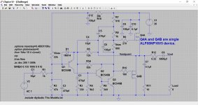
Q2 and Q3 can be a single darlington (hence the name diyAudio Trio) but its much much better with a discrete two transistor arrangement. The output FET (just the one) is a unique single device containg an N and P channel FET.
So that's my idea for a simple low component count discrete design.
Q2 and Q3 can be a single darlington (hence the name diyAudio Trio) but its much much better with a discrete two transistor arrangement. The output FET (just the one) is a unique single device containg an N and P channel FET.
So that's my idea for a simple low component count discrete design.
Attachments
Pity you despise chipamps, although if you think about it, it's still an all bipolar amp, just packaged inside a single case for your convenience, but that does not change the way it works a single bit.
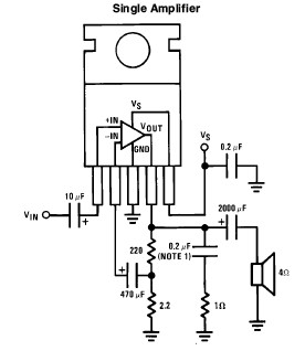
This is justly famous Craig Anderton's Guitar Amp.
Not a real "full design" but a clever parts value choice into what is basically the datasheet example to increase gain and input impedance so it can be driven straight from a guitar (no preamp needed) ... what is not the case with the above posted example.
Notice a range of values is suggested for R2 and R3, gain being : (R3/R2)+1 , so maximum gain (if needed) would be: 4700/22= ~250X ... more than enough to make the amp distort if so needed.
For general purpose use I'd aim at around 20X gain.
Volume and tone controls?
The ones already in your guitar, of course!! 😉
FWIW this is the original datasheet suggested schematic:
Download and read the full datasheet http://pdf1.alldatasheet.es/datashe...47UORlHDyRHOIpa/1XXyxeogyRIHpM+/datasheet.pdf which not only shows you the full bipolar internal circuit (some 18 transistors inside) but also suggests a PCB layout, if you want to cook your own 🙂
A very good project to get your feet wet building a useful and good sounding guitar amp.
An externally hosted image should be here but it was not working when we last tested it.
Some ideas from the past.
Now we are talking!
JMFahey, i thought about it myself. I just happen to have a bunch of tda2030s salvaged from an old "home cinema" subwoofer. It would certainly do the job, probably quite well, but i want to make something more challenging, and probably better sounding. I'm thinking Class A all the way, single ended or not. But not anything overcomplicated! I was hoping that about 4 bjts would do the trick.
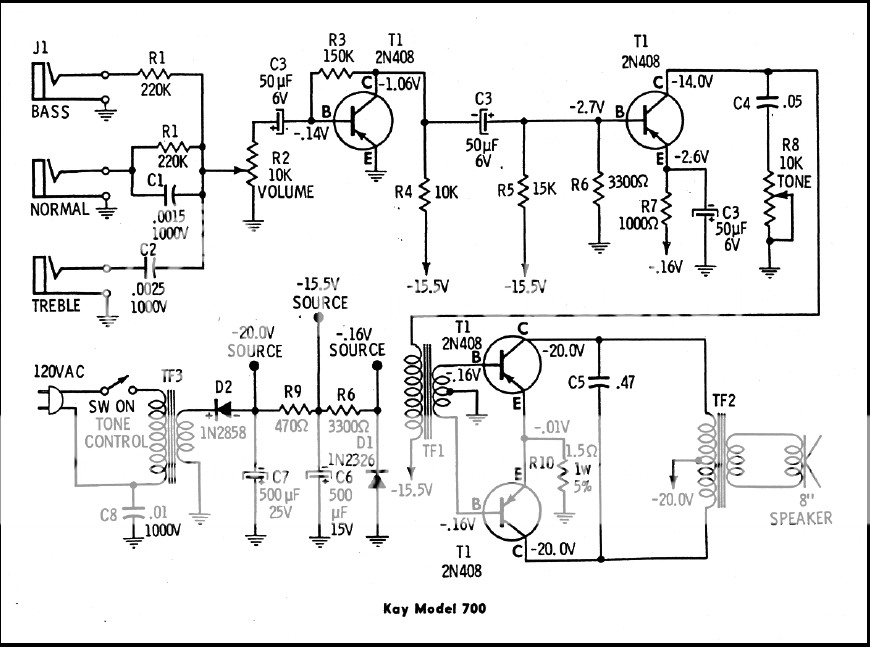
Printer2, an output transformer would be too much of a trouble for a simple build. But the power amplifier stage of the Gibson amp is totally in the game.
By the way, an adjustable output impedence would come in handy, maybe through an internal pot or something.
JMFahey, i thought about it myself. I just happen to have a bunch of tda2030s salvaged from an old "home cinema" subwoofer. It would certainly do the job, probably quite well, but i want to make something more challenging, and probably better sounding. I'm thinking Class A all the way, single ended or not. But not anything overcomplicated! I was hoping that about 4 bjts would do the trick.
Printer2, an output transformer would be too much of a trouble for a simple build. But the power amplifier stage of the Gibson amp is totally in the game.
By the way, an adjustable output impedence would come in handy, maybe through an internal pot or something.
Now we are talking!
JMFahey, i thought about it myself. I just happen to have a bunch of tda2030s salvaged from an old "home cinema" subwoofer. It would certainly do the job, probably quite well, but i want to make something more challenging, and probably better sounding. I'm thinking Class A all the way, single ended or not. But not anything overcomplicated! I was hoping that about 4 bjts would do the trick.
Printer2, an output transformer would be too much of a trouble for a simple build. But the power amplifier stage of the Gibson amp is totally in the game.
By the way, an adjustable output impedence would come in handy, maybe through an internal pot or something.
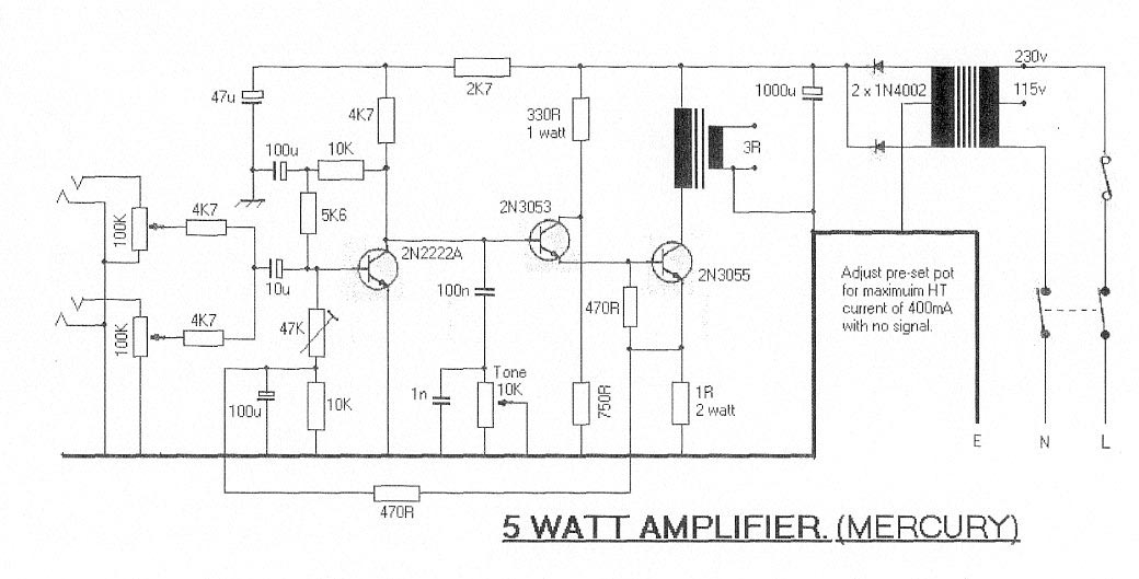
More to show how the cat was skinned before.
Took me a while to understand that remark!🙂More to show how the cat was skinned before.
Anyway, the Red circuits 10watt amplifier is closer to what i am after, but maybe it is a little less minimalistic (aka more complex than i dream).
Took me a while to understand that remark!🙂
Anyway, the Red circuits 10watt amplifier is closer to what i am after, but maybe it is a little less minimalistic (aka more complex than i dream).
Life is like that. Delete the overdrive switch, select capacitor (or not) to taste. Cut and volume control disappears, no need for C7 then. Delete one input jack and C1 (I think). R8, D7 are just an indicator light, Does not add to the circuit but don't complain when you leave on the amp. So there, got rid of ten parts for you.
Now I don't know how well the circuit works and you may have to tweak a thing or two or maybe not. Just looked for a few schematics with a lower parts count and did not read much further. Maybe someone else can roll with the ball now, I have a few projects to do.
- Status
- Not open for further replies.
- Home
- Live Sound
- Instruments and Amps
- How to build a simple, low power guitar amp