Mistakes are part of learning...
-Gnobuddy
Thank you Gnobuddy!
I find your advice and your general stance (either on electronics or in life) very helpful.
I don't have a desoldering station or gun, but i do have lots of braided copper mesh. I will salvage what i can, but still, i think i will start from scratch this time, because the components are really cheap (i probably have everything in my parts bin) and the old pcbs are, well, like your baby first steps example... I want to make something more professional looking (and working...😀)
Of course, failure is always an option.
Most of the time I de-solder without a de-soldering station.
First step: Heat up the soldering joint and hard kick the pcb against the table: Most of the solder flies away.
Second step: do the cleaning with desoldering copper braid.
The first step saves you lots of desoldering copper braid.
First step: Heat up the soldering joint and hard kick the pcb against the table: Most of the solder flies away.
Second step: do the cleaning with desoldering copper braid.
The first step saves you lots of desoldering copper braid.
I admit i have done it several times in the past, but i feel it's kind of dangerous... One wouldn't like a blob of 300c (++) melted alloy landing... well, anywhere near himselfMost of the time I de-solder without a de-soldering station.
First step: Heat up the soldering joint and hard kick the pcb against the table: Most of the solder flies away.
Second step: do the cleaning with desoldering copper braid.
The first step saves you lots of desoldering copper braid.
I would advise at least eye protection.
Fastest way I depopulated a board was to blow hot air from a heat gun on the solder side and then hit the bench with the board which sent the solder flying.
The fastest way to get down from the 10th floor is to jump out of the window. That doesn't mean it's a good way, though! 😱
Molten solder is hot enough to cause third-degree burns. Spraying it around the work area is just a bad, bad, bad idea, for so many reasons that it's not even worth trying to list them.
I care about your safety (all of you out there). Please be careful!
-Gnobuddy
Molten solder is hot enough to cause third-degree burns. Spraying it around the work area is just a bad, bad, bad idea, for so many reasons that it's not even worth trying to list them.
I care about your safety (all of you out there). Please be careful!
-Gnobuddy
FWIW when I was young, transistors were relatively expensive (that should give you some hint about the Geological era involved 😉 ) so we young experimenters, permanently short of funds, sometimes used a similar method to get tons of (experimenter's grade) transistors for, literally, peanuts, the infamous "burn and slap" .
There was this Surplus guy who sold Elctronics, including tons of Military equipment, by the kilo.
So we went and bought an IBM mainframe computer board
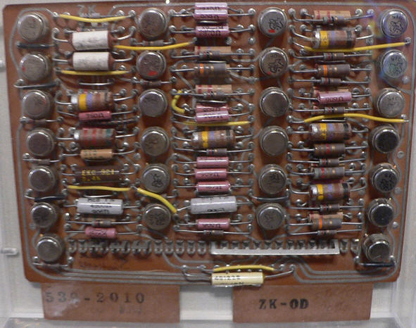
in fact some 8X larger than this one for a couple bucks, covered the kitchen table with newspaper, melted solder with a propane torch and slapped the board hard against the table.
What's amazing is that practically all transistors still worked after that 😱
Won't comment on the joy of Sherman tank (WW2) radio transceivers, pilot rescue crank operated radio transmitters (complete with (rotten) balloon and Helium bottle to inflate it), Lancaster bomber radio direction finders, Radar PPI displays (source of cathode ray tubes for homemade oscilloscopes) and other beauties.
There was this Surplus guy who sold Elctronics, including tons of Military equipment, by the kilo.
So we went and bought an IBM mainframe computer board
in fact some 8X larger than this one for a couple bucks, covered the kitchen table with newspaper, melted solder with a propane torch and slapped the board hard against the table.
What's amazing is that practically all transistors still worked after that 😱
Won't comment on the joy of Sherman tank (WW2) radio transceivers, pilot rescue crank operated radio transmitters (complete with (rotten) balloon and Helium bottle to inflate it), Lancaster bomber radio direction finders, Radar PPI displays (source of cathode ray tubes for homemade oscilloscopes) and other beauties.
You might prefer more gain than two gain stages will give you. By putting a volume control after the first stage (rather than just using the one on the guitar), turning down the volume will also turn down most of the hiss noise. Put a passive Rf filter at the input, since the guitar acts as an antenna picking up Rf energy which the circuit is likely to detect (AM demodulate) creating I.M. products. I rec a 10K in series and a 330p cap to ground (for -3dB at 24kHZ if guitar source Z is 10k ohms). Then a .01u coupling cap and a 1M ohm R to ground (which most guitar pickups are designed for). IMO tone controls are a must. Flat is rarely optimal, especially for guitars. I recommend Baxandall tone circuits, and a high pass shelf with the transition near 1kHZ.Hi everyone,
as the title suggests, i would like to build a simple, low power guitar amp. I have been thinking this for a long time, but my interest became a desire when i saw and build this circuit, which is an ultra simple, ultra clean, headphone amp. http://www.diyaudio.com/forums/head...ansistor-headphone-amplifier.html#post4698732
So, i would like to make something similar, but able to drive an 8 ohm speaker at a 1 to 2 watts without distortion (for practice use and maybe recording).
I consider this a challenge. I would like for the build to meet the following parameters:
-Low power output (up to 5 watts).
-Completely discrete semiconductor design.
-Only bjt transistors, preferably only NPNs (i hate fets, for reasons).
- Completely Class A operation.
-No tone controls, no gain or distortion features. Only clean, raw, undistorted guitar signal amplification to drive a speaker.
-Preferably no output capacitor (direct connection) with a symmetrical power supply.
-Preferably, only an on/off switch. Not even a volume pot! (I would like to adjust the volume from the guitar).
-Finaly, no audible distortion up to the rated power.
Does something like that already exist (as a schematic)? If not, i would very much appreciate any input on how to modify the headphone amp (increase bias?, add a stage or two?) in order to achieve my goal.
Thanks for any help!
If you load a typical guitar pickup (Strats, Gibsons, etc.) with less than 1M ohm, you lose treble extension, and it can sound "honky" and muffled. Since bipolars draw significant base currrent, they have lower input impedance than 1M. Because of that, I'd definitely use either a FET or a vacuum tube for the input stage. Piezo pickups on some acoustic guitars are even more sensitive to load Z.
Bob, by post #22 we found out that the OP was in fact looking for (his words) "a buffer with some gain between a pedalboard and a speaker".
Since the guitar will already be buffered by whatever is on that pedalboard, that eases the input impedance requirements quite a bit, and all-BJT became a practical proposition at that point.
-Gnobuddy
Since the guitar will already be buffered by whatever is on that pedalboard, that eases the input impedance requirements quite a bit, and all-BJT became a practical proposition at that point.
-Gnobuddy
- Status
- Not open for further replies.
- Home
- Live Sound
- Instruments and Amps
- How to build a simple, low power guitar amp