Right! My first experience with plates from Front Panel Express... it won't be my last!Looks like they've made a top notch job on the panels.
Hello!
If there is also a wire marked +6 then they are MK II. The MK I and the MK III had primary markings of '+', '-', '++', and '--'. Likely you just will tuck that +6 wire away - most systems don't need the gain and the load for your source is a bit easier when not using the +6db gain mode. There may also be one extra tap wire than you have room for on your switch and if that is the case plan which one to skip before you start wiring - usually skip one of the lower taps like -43db but if you have horn speakers then you could skip one up at the top like maybe the 2db tap.
BTW - Nice looking front and back panel plates!
Have fun with the project.
Thansk!
John
Hi John! Thanks for the information - I wish I had taken better notes when I looked them over yesterday... I'll take another look later.Hello!
If there is also a wire marked +6 then they are MK II. The MK I and the MK III had primary markings of '+', '-', '++', and '--'. Likely you just will tuck that +6 wire away - most systems don't need the gain and the load for your source is a bit easier when not using the +6db gain mode. There may also be one extra tap wire than you have room for on your switch and if that is the case plan which one to skip before you start wiring - usually skip one of the lower taps like -43db but if you have horn speakers then you could skip one up at the top like maybe the 2db tap.
BTW - Nice looking front and back panel plates!
Have fun with the project.
Thansk!
John
By the way, this current project is up against some stiff competition here! 🙂
Attachments
Hello!
Have fun and feel free to send along any questions.
Like the circle cutout on the PRM-1 you used on the 'other' project!
Thansk!
John
Have fun and feel free to send along any questions.
Like the circle cutout on the PRM-1 you used on the 'other' project!
Thansk!
John
Thank you, John!
I've just double-checked and these transformers have no +6 wire. There's a total of 22 wires here: 2 black (+ and -), 19 white (marked from 0 to -46) and one additional white (marked -).
I've just double-checked and these transformers have no +6 wire. There's a total of 22 wires here: 2 black (+ and -), 19 white (marked from 0 to -46) and one additional white (marked -).
Hello!
Sounds like maybe an early rev mk I. I recall that all the ones I had here were dual primary coils - for 6 db gain mode. There were some early ones with fewer taps like the one you have. Wire it with + to the hot input and - to the gnd side. Then the taps to the switch. Check that white wire marked - for any connection to the primary or secondary. If it has no connection then it is a screen wire and can be grounded. If it has a connection report back and we can noodle out what it might be.
Btw - Do you know the origin of those transformers?
Thanks!
John
Funny you should ask, John. The previous owner said he got them from you. 🙂
Just confirmed that the white - wire is connected to the secondary winding. Five bucks says it's the "blank" wire that goes to output cold as in the spec sheet:
http://web.archive.org/web/20070710172959/http://www.stevens-billington.co.uk/page102.htm
Just confirmed that the white - wire is connected to the secondary winding. Five bucks says it's the "blank" wire that goes to output cold as in the spec sheet:
http://web.archive.org/web/20070710172959/http://www.stevens-billington.co.uk/page102.htm
Hello!
I expect then that I did supply them - I guess I should recall better! In my defense it was well over 10 years back now though when I started selling them and they underwent a few changes along the way....
These must be early MK I transformers - the 19 taps tell that. Not too long after I started working with S&B I requested that they put a few more taps on - to better match most 23 position switches so most the ones I supplied had 23 (or 24 counting the -) secondary taps. The doc you link to was written by Thorsten early on so it shows the 19 taps like the unit you have.
The '-' will indeed be the bottom of the secondary and as shown it connects to the gnd side of the output jack.
You may connect a switch between the primary - and the secondary - so you can select floating the ground or connecting input ground to output ground. This connection can also simply be hardwired if your system prefers that hard grounding mode. If the system is quiet then you have the best connection. Some systems quite prefer one gnd mode or another and some are quiet either way.
There was typically also a 'screen' wire that would be connected ground but it could be on those early ones that connection was made internally. on the link you send it is listed as the black wire connected to the lamination. Since it does not exist on the units you have I suggest that you skip that connection.
Thanks!
John
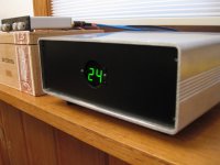
I recently boxed up my project and I'm pretty happy with how it turned out. I still want to paint or powdercoat the enclosure itself, but I've been enjoying it!
🙂


🙂
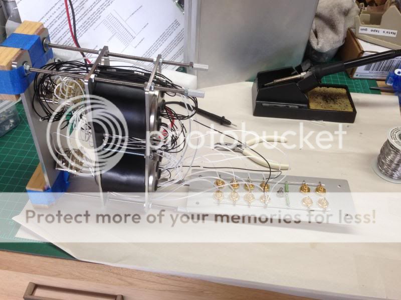
Inside, it's not as pretty but I'm pleased with the transformer mounting solution I came up with.
Congratulations. Very beautiful.
Are you pleased with the sound? Or with the lack of it I better say... 🙂
Cheers,
M.
Are you pleased with the sound? Or with the lack of it I better say... 🙂
Cheers,
M.


Hi. Can you send me schematic of tx102? ThanksSend me an e-mail, and I'll send you a better resolution copy.
Hi, i have tried this way and no sound? How to change polarity?ThanksHi,
Yes, that seems all correct. If at the beginning you do not get any sound or very little in AVC connection you know you have the primary polarity wrong.
You understand wrongly. The input impedance remains identical, discounting any parasitic DCR etc.
Same too....
MSG
Sayonara
- Home
- Design & Build
- Parts
- how to build a pre using S&B TX-102 transformers