Whereas a TVC has the i/p to the primary and the o/p from the secondary an autotransformer / autoformer / AVC, only needs one coil - the i/p goes in at the top and the o/p is taken from one of the taps on the same winding.
So for an existing TVC the simplest ( but not the only ) way to convert to an AVC is to simply connect the i/p signal across the secondary winding.
The disadvantage is that i/p to o/p earth isolation is lost and useful ultrasonic roll-off may be reduced.
The advantage, at least for the S&B 102mk2 is a dramatic difference in sound between these two connection methods.
Yes, I agree that a TVC has a soft sound
The AVC sound could never be called soft. Everything - bass, mid & treble - sound more immediate and alive.
THIS IS A SERIOUS IMPROVEMENT IN SOUND we are talking about ( unless your source needs softening...😉 )
mike
mikelm said:Whereas a TVC has the i/p to the primary and the o/p from the secondary an autotransformer / autoformer / AVC, only needs one coil - the i/p goes in at the top and the o/p is taken from one of the taps on the same winding.
So for an existing TVC the simplest ( but not the only ) way to convert to an AVC is to simply connect the i/p signal across the secondary winding.
The disadvantage is that i/p to o/p earth isolation is lost and useful ultrasonic roll-off may be reduced.
The advantage, at least for the S&B 102mk2 is a dramatic difference in sound between these two connection methods.
Yes, I agree that a TVC has a soft sound
The AVC sound could never be called soft. Everything - bass, mid & treble - sound more immediate and alive.
THIS IS A SERIOUS IMPROVEMENT IN SOUND we are talking about ( unless your source needs softening...😉 )
mike
Hello mike,
I am wondering about impedance mismatch ...
Cheers
Christian.
Konnichiwa,
Before I forget, I hope you terminated the primary in parallel with the secondary, for your autoformer implementation of the 102. If you did not, you may just be hearing the effects of a HUGE ultrasonic peak, not of AVC vs. TVC.
Sayonara
mikelm said:The advantage, at least for the S&B 102mk2 is a dramatic difference in sound between these two connection methods.
Before I forget, I hope you terminated the primary in parallel with the secondary, for your autoformer implementation of the 102. If you did not, you may just be hearing the effects of a HUGE ultrasonic peak, not of AVC vs. TVC.
Sayonara
Kuei Yang Wang said:Konnichiwa,
Before I forget, I hope you terminated the primary in parallel with the secondary, for your autoformer implementation of the 102. If you did not, you may just be hearing the effects of a HUGE ultrasonic peak, not of AVC vs. TVC.
Sayonara
Hello Kuei,
so let me conclude:
keep wired as TVC but connect the whole secondary winding to the primary "+" ... Schematics appreciated...
How will this affect the input and output impedance?
Did you try this as well?
Konnichiwa,
In effect - yes.
Sorry, I don't have one.
Not at all really, possbly the output impedance is slightly lower..
Yes, in fact I only tried it that way. Just measure the results of doing it the other way.
Sayonara
krishu said:so let me conclude:
keep wired as TVC but connect the whole secondary winding to the primary "+" ...
In effect - yes.
krishu said:Schematics appreciated...
Sorry, I don't have one.
krishu said:How will this affect the input and output impedance?
Not at all really, possbly the output impedance is slightly lower..
krishu said:Did you try this as well?
Yes, in fact I only tried it that way. Just measure the results of doing it the other way.
Sayonara
Kuei Yang Wang said:Konnichiwa,
Before I forget, I hope you terminated the primary in parallel with the secondary, for your autoformer implementation of the 102. If you did not, you may just be hearing the effects of a HUGE ultrasonic peak, not of AVC vs. TVC.
Sayonara
Thanks for the warning - so far my tweeters are still intact.
I spoke to Jonathon about AVC mode a few weeks ago and he said that it might sound better if the primary was either in series or parallel with the secondary.
He did not mention ultrasonic peaks so I did not experiment yet
Tonight I tried the parallel version and so far I cannot hear that much difference but I will try all three modes over the next few days and see if I can notice a difference.
mike
Kuei Yang Wang said:Konnichiwa,
Sorry, I don't have one.
Sayonara
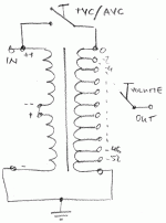
Hello,
there is a schematic in the attachment; could anyone please validate that I understood the difference between TVC and AVC correctly ...
Note: VTC/ATC-Switch open=VTC; closed=ATC
As I understand the input impedance of an ATC is much lower than compared to TVC because the input imp. of the power amp has to be considered (in parallel); How about the output impedance of the AVC compared to the TVC?
Gruß
Christian.
Attachments
Hi Krishu
Schematic seems fine to me. I am also going to try it over the weekend.
Impedance wise i don't see why the input impedance would be any different than straight TVC. Output should be marginally lower.
Schematic seems fine to me. I am also going to try it over the weekend.
Impedance wise i don't see why the input impedance would be any different than straight TVC. Output should be marginally lower.
analog_sa said:Hi Krishu
Schematic seems fine to me. I am also going to try it over the weekend.
Impedance wise i don't see why the input impedance would be any different than straight TVC. Output should be marginally lower.
Thanks,
Input impedance at 20kHz ist about 50K when configured as TVC. Considering 25K input impedance of the power amp the effective input impedance seen by the source would be about 50K||25K@1kHz when configured as AVC.
Cheers
Christian.
Input impedance at 20kHz ist about 50K when configured as TVC
Sorry, i don't understand the above. Why at 20kHz? Surely at such a high frequency it's just a matter of transforming impedances, ie it will only depend upon the power amp input impedance and the position of the TVC.
Hi,
Yes, that seems all correct. If at the beginning you do not get any sound or very little in AVC connection you know you have the primary polarity wrong.
You understand wrongly. The input impedance remains identical, discounting any parasitic DCR etc.
Same too....
MSG
Sayonara
krishu said:there is a schematic in the attachment; could anyone please validate that I understood the difference between TVC and AVC correctly ...
Note: VTC/ATC-Switch open=VTC; closed=ATC
Yes, that seems all correct. If at the beginning you do not get any sound or very little in AVC connection you know you have the primary polarity wrong.
krishu said:As I understand the input impedance of an ATC is much lower than compared to TVC
You understand wrongly. The input impedance remains identical, discounting any parasitic DCR etc.
krishu said:How about the output impedance of the AVC compared to the TVC?
Same too....
MSG
Sayonara
Konnichiwa,
You need to account for parasitic primary capacitance. It should be below 100pF, but JB would have to measure it, he is kinda busy right now. Now 100pFshould translate into around 80KOhm @ 20KHz.
Sayonara
analog_sa said:Sorry, i don't understand the above. Why at 20kHz? Surely at such a high frequency it's just a matter of transforming impedances, ie it will only depend upon the power amp input impedance and the position of the TVC.
You need to account for parasitic primary capacitance. It should be below 100pF, but JB would have to measure it, he is kinda busy right now. Now 100pFshould translate into around 80KOhm @ 20KHz.
Sayonara
Konnichiwa,
Yup, that is exactly what I am refering to.
Let us consider the TX-102 MKIII as having a primary inductance of 400H and a parasitic capacitance of 100pF. And let us also consider our load is a 100K//100pF Tube Amp with a 100pF shunt capacitance in the interconnecting cable.
Let us now consider the effective input impedance of our TX-102 at 0db, 6db and 20db attenuation.
Let us start with direct unity gain:
Zl for 400H @ 20Hz is around 50KOhm and 2.5MOhm @ 1KHz
Zc for 300pF (input capacitance of Amp, connecting cable and primary capacitance) @ 20KHz is around 26K and 530K @ 1KHz
All of this in parallel with 100K leads to an input impedance of around 81kOhm @ 1KHz and 33KOhm @ 20Hz and 21KOhm @ 20KHz.
For the 6db attenuation case:
Zl for 400H @ 20Hz is around 50KOhm and 2.5MOhm @ 1KHz
Zc for 150pF (input capacitance of Amp, connecting cable divided by 4 + 100pF primary capacitance) @ 20KHz is around 53KOhm and 1.06MOhm @ 1KHz
All of this in parallel with 400KOhm (transformed up 100K load) leads to an input impedance of around 260kOhm @ 1KHz and 44KOhm @ 20Hz and 47KOhm @ 20KHz.
For the 20db attenuation case:
Zl for 400H @ 20Hz is around 50KOhm and 2.5MOhm @ 1KHz
Zc for 102pF (input capacitance of Amp, connecting cable divided by 100 + 100pF primary capacitance) @ 20KHz is around 78K and 1.56MOhm @ 1KHz
All of this in parallel with 10MOhm (transformed up 100K load) leads to an input impedance of around 878kOhm @ 1KHz and 50KOhm @ 20Hz and 77.5KOhm @ 20KHz.
Obviously, in all cases the inductive/capacitive reactance is well above the specified 10K nominal impedance of the TX-102, but the differences at high and low frequencies are material. Just for fun the same calculation with a 10K//1nF IEC load, which was basically the "design normal" load for the TX-102....
Let us start with direct unity gain:
Zl for 400H @ 20Hz is around 50KOhm and 2.5MOhm @ 1KHz
Zc for 1100pF (IEC Load and primary capacitance) @ 20KHz is around 7.2K and 145K @ 1KHz
All of this in parallel with 10K leads to an input impedance of around 9.3kOhm @ 1KHz and 8.3KOhm @ 20Hz and 4.2KOhm @ 20KHz.
For the 6db attenuation case:
Zl for 400H @ 20Hz is around 50KOhm and 2.5MOhm @ 1KHz
Zc for 350pF (IEC Load capacitance / 4 and primary capacitance) @ 20KHz is around 53KOhm and 1.06MOhm @ 1KHz
All of this in parallel with 40KOhm (transformed up 10K load) leads to an input impedance of around 36kOhm @ 1KHz and 22KOhm @ 20Hz and 14.5KOhm @ 20KHz.
For the 20db attenuation case:
Zl for 400H @ 20Hz is around 50KOhm and 2.5MOhm @ 1KHz
Zc for 110pF (IEC Load capacitance / 100 and primary capacitance) @ 20KHz is around 72K and 1.45MOhm @ 1KHz
All of this in parallel with 1MOhm (transformed up 10K load) leads to an input impedance of around 479kOhm @ 1KHz and 48KOhm @ 20Hz and 67KOhm @ 20KHz.
Again, the parasitic elements actually belonging to the TX-102 MKIII are well out of contention compared to the nominal impedance of the TX-102.
In fact, based on inductive and capacitive reactance of the TX-102 MKIII one might even be reasonable to re-classify the TX-102 MKIII as having a 50KOhm effective impedance if we want to be comparable to a resistor type atenuator.
Sayonara
analog_sa said:This i understand well. My question was in the context of determining the input impedance.
Yup, that is exactly what I am refering to.
Let us consider the TX-102 MKIII as having a primary inductance of 400H and a parasitic capacitance of 100pF. And let us also consider our load is a 100K//100pF Tube Amp with a 100pF shunt capacitance in the interconnecting cable.
Let us now consider the effective input impedance of our TX-102 at 0db, 6db and 20db attenuation.
Let us start with direct unity gain:
Zl for 400H @ 20Hz is around 50KOhm and 2.5MOhm @ 1KHz
Zc for 300pF (input capacitance of Amp, connecting cable and primary capacitance) @ 20KHz is around 26K and 530K @ 1KHz
All of this in parallel with 100K leads to an input impedance of around 81kOhm @ 1KHz and 33KOhm @ 20Hz and 21KOhm @ 20KHz.
For the 6db attenuation case:
Zl for 400H @ 20Hz is around 50KOhm and 2.5MOhm @ 1KHz
Zc for 150pF (input capacitance of Amp, connecting cable divided by 4 + 100pF primary capacitance) @ 20KHz is around 53KOhm and 1.06MOhm @ 1KHz
All of this in parallel with 400KOhm (transformed up 100K load) leads to an input impedance of around 260kOhm @ 1KHz and 44KOhm @ 20Hz and 47KOhm @ 20KHz.
For the 20db attenuation case:
Zl for 400H @ 20Hz is around 50KOhm and 2.5MOhm @ 1KHz
Zc for 102pF (input capacitance of Amp, connecting cable divided by 100 + 100pF primary capacitance) @ 20KHz is around 78K and 1.56MOhm @ 1KHz
All of this in parallel with 10MOhm (transformed up 100K load) leads to an input impedance of around 878kOhm @ 1KHz and 50KOhm @ 20Hz and 77.5KOhm @ 20KHz.
Obviously, in all cases the inductive/capacitive reactance is well above the specified 10K nominal impedance of the TX-102, but the differences at high and low frequencies are material. Just for fun the same calculation with a 10K//1nF IEC load, which was basically the "design normal" load for the TX-102....
Let us start with direct unity gain:
Zl for 400H @ 20Hz is around 50KOhm and 2.5MOhm @ 1KHz
Zc for 1100pF (IEC Load and primary capacitance) @ 20KHz is around 7.2K and 145K @ 1KHz
All of this in parallel with 10K leads to an input impedance of around 9.3kOhm @ 1KHz and 8.3KOhm @ 20Hz and 4.2KOhm @ 20KHz.
For the 6db attenuation case:
Zl for 400H @ 20Hz is around 50KOhm and 2.5MOhm @ 1KHz
Zc for 350pF (IEC Load capacitance / 4 and primary capacitance) @ 20KHz is around 53KOhm and 1.06MOhm @ 1KHz
All of this in parallel with 40KOhm (transformed up 10K load) leads to an input impedance of around 36kOhm @ 1KHz and 22KOhm @ 20Hz and 14.5KOhm @ 20KHz.
For the 20db attenuation case:
Zl for 400H @ 20Hz is around 50KOhm and 2.5MOhm @ 1KHz
Zc for 110pF (IEC Load capacitance / 100 and primary capacitance) @ 20KHz is around 72K and 1.45MOhm @ 1KHz
All of this in parallel with 1MOhm (transformed up 10K load) leads to an input impedance of around 479kOhm @ 1KHz and 48KOhm @ 20Hz and 67KOhm @ 20KHz.
Again, the parasitic elements actually belonging to the TX-102 MKIII are well out of contention compared to the nominal impedance of the TX-102.
In fact, based on inductive and capacitive reactance of the TX-102 MKIII one might even be reasonable to re-classify the TX-102 MKIII as having a 50KOhm effective impedance if we want to be comparable to a resistor type atenuator.
Sayonara
Kuei Yang Wang said:Hi,
You understand wrongly. The input impedance remains identical, discounting any parasitic DCR etc.
Sayonara
Hello,
I am a bit confused by this but won't mind as long as it does sound nice 😉 I'll write you an email in German to make things more clear as this is impossible for me to write in English - sorry.
Why do Bent audio and the others not tell about the AVC option? Or did I miss it? What's the disadvantage?
Regards
Christian.
Hello again,
Kuei Yang Wang found my mistake ... the source does not "see" the input impedance of the power amp because I did not take the attenuation into my considerations...
Regards
Christian.
Kuei Yang Wang found my mistake ... the source does not "see" the input impedance of the power amp because I did not take the attenuation into my considerations...
Regards
Christian.
Well, last night I tried the exact diagram that has been posted recently.
I think that Kuei may have been correct. The sound has a different charactor than before - don't get me wrong, it sounds really great but... it is more smooth again but still very detailed & refined - but.... I have been doing a lot of work on my CD player aswell so it's a bit hard to know what is causing what.
paralleling the coils seems to reduce the volume.
My original configuration was unusual. I was injecting the i/p signal into the secondary only, but two taps down from the top.
One end of half of the primary was connected to earth the other half was completely disconnected.
I have no idea what kind of bizarre effect this may have been causing.
Once I have listened to this for a few days I will try the primary in series with the secondary.
mike
Kuei,
What is the difference between having a huge amount of the secondary out of cct by having the volume turned down low in a TVC configuration and having the input going straight to the secondary and the primary earthed one end and disconnected at the other end ?
Is is just a bit worse or is it a Cardinal Sin ???
mike
- Home
- Design & Build
- Parts
- how to build a pre using S&B TX-102 transformers