I was using power supply ground instead of digital ground. It is starting to make more sense now. I have 12V at the emitter, collector, both sides of R9 and 10V at pin 4 of U2. I need to be looking at Q6.
All the isolation on the grounds makes these good in operation but it gets tricky testing! Yes it looks like your issue is in the area of Q6. It's base gets a 5V signal from the control board to turn on through R11 which in turn should ground the input of U2.
If you find pin 4 of U2 is actually being grounded but the output fets aren't turning on look for a short between the gate and the source on Q8 and Q9 shorting the output of U2. This happens quite often and is hard to see.
If you find pin 4 of U2 is actually being grounded but the output fets aren't turning on look for a short between the gate and the source on Q8 and Q9 shorting the output of U2. This happens quite often and is hard to see.
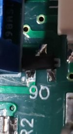
Very hard to see, but the base of Q6 isn't attached to it's pad. Resoldered and everything is working perfectly.
1 more question, can I power both DC boards from the rails of one channel, or should I power each board separetely from each channel board?
You have literally spent most of today answering my crazy questions. I can't thank you enough!!! if you need someone to write testimonies or reviews let me know, it's the least I could do.
Good to hear you have it working! The detection circuits should connect directly to the power supply for the amp channel it's monitoring. If you connect to the amplifier itself you may see some false triggering due to voltage fluctuations.
I'm using one of your Dual Board power supplies for two channels, I'll connect to that somewhere.
Again, I can't thank you enough, I've learned a lot doing this!
Again, I can't thank you enough, I've learned a lot doing this!
Yes. It doesn't happen always. My guess is that it detects DC before the SSR so it doesn't do any harm to the speakers 'cause the SSR (on the OPS module) are closed.Is the protection board shutting the amp down when this happens?
Those versions seem to be sensitive to static charges. It seems to be more from the supply rails to the DC detection circuit. In normal operation it works well, it just doesn't like to be tampered with in operation.
Thanks jwilhelm for the info. I'll check the DC offset at the speakers, if it's OK I would only have this odd indication for few seconds.
Thanks! I'll post some pictures after this weekend, waiting on a couple nuts and a switch to finish the project.
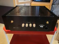
You mean nuts to fit the binding posts? If so where did you find them? I've given up and started machining my own.
Place called Little Machine Shop in California.
M8X0.75 thread nuts and washers
Search For... - LittleMachineShop.com
M8X0.75 thread nuts and washers
Search For... - LittleMachineShop.com
Good morning everyone, Valery Zaichenko sent me the Gerber and firmware files (21st Century Protection Board) by private email a while ago, but I accidentally deleted them from my email inbox, unfortunately he can no longer send them to us. I would like to know if anyone can make them available to me, because I have a project here where I will have to build a protection for the amplifier. I am very grateful!
Thanks for replying.jwilhelmI ,don't remember the version he sent me, but I'll use it on the (Q17-Mini (stef1777)), and it might be the latest version. I think it will work, if I remember correctly, it had temperature sensing.
- Home
- Amplifiers
- Solid State
- How to build a 21st century protection board
