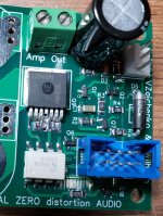
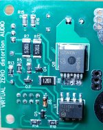
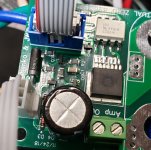
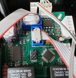
Success getting the bootloader loaded! I used the toaster oven and used a timer and set the temps approximately, it lined up perfectly. Still wouldn't work because I set of pins didn't have enough solder paste, so used the soldering iron, still wouldn't work, found a VERY small solder bridge between two pins and it worked. Thanks for everyones help. The rest of the chips look way easier.
Is C7 and C31 used on this board? They aren't in the BOM. Also, do you have a part number for the heatsink used for the regulators?
I finally got around to getting my honey badger boards finished, I have one channel completed and working perfectly. I'm having trouble with the DC Detection boards and it's my fault. I had the polarity switched on one board from the rail voltages and I had both boards 8-pin ribbon cable from the control board installed backwards, Pin 1 was in the 7-8 position and so on.
Now when I power up with power to the boards and the 8-pin ribbon connector connected it immediately goes into DC detected and shuts down the amp. I do not have the amp outputs connected to the boards, so it's not seeing any DC.
What should I check first?
BTW, I did double check all the connectors and they are correct now.
I've got the feeling the reversed power did not harm anything, but the reversed ribbon may have.
I checked R8 and it has 8mA going through it. I also checked R7 and R12, both have 8mA going through them and 15 volts on the diode side. Now I'm fairly sure the reversed power connection didn't do any damage. The problem must be in the top half of the wiring diagram.
I'm wondering if I smoked Q6 by putting 12 volts on it's base. I don't think I smoked Q5 because it would have put ground on both it's emitter and collector, no current flow.
Normally connecting the ribbon cable backwards doesn't cause any damage. It's likely best to start with checking out Q5 circuit, that's what signals a DC condition to the control board. With rail voltage and the ribbon cable connected is voltage between pin 5 and pin 7 of U1 low (around 1VDC)?
Last edited:
One thing to keep in mind while testing, if you connect the ribbon cable while the control board is in speaker on mode the detection will trip instantly. It needs to be connected prior to running the power on cycle.
Thanks for the last tip, did not know that, but have been starting with everything hooked up. I have .8V between pin 5 and 7 on U1. I was also able to test Q5 with a transistor checker in circuit, it's good. Of course it trips right at the end of the start-up process.
With .8V at pin 7 Q5 shouldn't be conduction, so pin 1 and 2 of the ribbon cable should have 5V present. Is it there?
- Home
- Amplifiers
- Solid State
- How to build a 21st century protection board


