The square pad on the board for the connector is pin 1. The notch (V) on the connector goes towards pin 1. The stripe on the cable is pin 1. It looks like you have the connector in the speaker relay board installed backwards. I can't tell which way you have it in the control board.
I'm going to stop, check all the ribbon connector and get them correct. Disregard all measurements taken previously and start over. When the ribbon was backwards it didn't trip.
I'll get back with you when I have everything triple checked and start over.
I'll get back with you when I have everything triple checked and start over.
yes, it's backwards according to the square pad. The top board mask is incorrect. It has pin 1 towards the outside. the square pin is towards the inside. I'll get that fixed and try it.
BTW, is there a way to insert a reset switch on the control board, I have V5.4? I'm getting tired of unplugging the amp every time it trips. Would make it easier once the amp is installed also, put the switch on the back.
BTW, is there a way to insert a reset switch on the control board, I have V5.4? I'm getting tired of unplugging the amp every time it trips. Would make it easier once the amp is installed also, put the switch on the back.
The board will reset automatically if you open the serial monitor window in the Arduino IDE. Just close it and reopen it every time you want to reset.
In the ICSP connector, pin 5 is reset, 6 is ground (end 2 pins opposite the square pad). Short them to reset.
In the ICSP connector, pin 5 is reset, 6 is ground (end 2 pins opposite the square pad). Short them to reset.
Last edited:
OK, all connectors and ribbon cables are now correct. The amp powers up and does not trip. problem is now neither board trips when DC is applied to the input connector. I ran all the way up to 5 Volts on each board.
I tried the boards separetly this time so I could keep things easier to troubleshoot.
I tried the boards separetly this time so I could keep things easier to troubleshoot.
When applying voltage for testing, you need to use the supply connection ground, not the amplifier connection or binding post ground. The circuit senses DC referenced to the power supply, not the binding posts.
Board #1 has 11.3 mA across R9 and trips when R3 to R4 is shorted.
Board #2 has 0 mA across R9 and also trips when r3 to R4 is shorted.
Board #2 has 0 mA across R9 and also trips when r3 to R4 is shorted.
Board #1 is working correctly, I was not using the right ground as you suspected.
Board #2 trips when 2 volts DC is applied to the speaker and ground terminals. Problem with that board, it is not connecting the speaker. Measures infinite ohms when started and not tripped. Must have something to do with R9 being 0mA.
Board #2 trips when 2 volts DC is applied to the speaker and ground terminals. Problem with that board, it is not connecting the speaker. Measures infinite ohms when started and not tripped. Must have something to do with R9 being 0mA.
The detection side of things is working then, now on to the relay circuit. With everything in normal operating state there should be around 1VDC on pin 6 of U1 You should have less than 1VDC at pin 4 of U2. You should have around 12V on the side of R9 that's towards Q10.
starting to make sense, checking power and ground on U2 and seeing if U1 is supplying control signal to base of Q10. I'll go check.
142 mV on pin 6 U1
11mV on R9, makes sense, Q10 not being turned on, right?
0mV on pin4 U2, makes sense, no voltage being supplied to the circuit.
are we back to Q5? Q5 checks good with a transistor tester and diode D6 is installed correctly, measure .6 volts one way, 1.4 volts the other way.
11mV on R9, makes sense, Q10 not being turned on, right?
0mV on pin4 U2, makes sense, no voltage being supplied to the circuit.
are we back to Q5? Q5 checks good with a transistor tester and diode D6 is installed correctly, measure .6 volts one way, 1.4 volts the other way.
It's looking like there's a problem with Q10. If pin 6 of U1 is pulling the base of Q10 low there should be voltage at R9.
Q10 also checks good and the LED's in U2 check good. I'm thinking U1 may be bad, or am I way off base.
Q 10 is a PNP so 142mV is indicating U1 is trying to ground it, correct? I'll check my connections between J3 and R9.
I wanted to ask this for a long time but I keep forgetting : when I close the amplifier the led most times starts blinking as if it detects DC. Is it normal ?
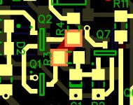
If you have 12V to the emitter of Q10 and the base is being pulled low there should be voltage at the collector of Q10. U1 is doing it's job, voltage should be low at pin 6. Possibly R14 is open or has a bad solder joint stopping base current from Q10.
You are referencing to the correct ground for sure? You need to be connecting your meter to digital ground for these measurements (pin 5 of U1).
You are referencing to the correct ground for sure? You need to be connecting your meter to digital ground for these measurements (pin 5 of U1).
I wanted to ask this for a long time but I keep forgetting : when I close the amplifier the led most times starts blinking as if it detects DC. Is it normal ?
Is the protection board shutting the amp down when this happens?
- Home
- Amplifiers
- Solid State
- How to build a 21st century protection board