Sorry for all the questions. I realize some of this has probably been asked but with all the design talk and software talk it gets lost.
I don't think I am understanding the 120Vac connections.
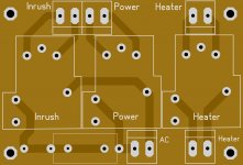
If I use the "Power" terminals under the "Start Input" as a switch, does this mean that the 120vac "Mains", "Rails", "Aux" and 12V transformer are hot all the time? It appears they are all direct parallel with each other and I don't see a way to switch any of them off.
Thanks, Terry
I don't think I am understanding the 120Vac connections.
If I use the "Power" terminals under the "Start Input" as a switch, does this mean that the 120vac "Mains", "Rails", "Aux" and 12V transformer are hot all the time? It appears they are all direct parallel with each other and I don't see a way to switch any of them off.
Thanks, Terry
There's a lot going on on these boards. Everyone has lots of questions when assembling these. For later versions of the board I have a detailed write up explaining the operation of every part to help people understand how they work. You and OS are the only people other than me to build this version, so I never did one for this.
120VAC is your mains feed from the wall. The 12V control transformer is live at all time. I added fuse holders for the power transformers here as well because it was convenient. They are live all the time. I used insulated fuse holders and covers for these.
120VAC is your mains feed from the wall. The 12V control transformer is live at all time. I added fuse holders for the power transformers here as well because it was convenient. They are live all the time. I used insulated fuse holders and covers for these.
Last edited:
OK that is what I thought. I don't like having the 12v transformer constantly running. I think I will just use a 120v switch for the Mains. Any issue with just shorting the Start Input "Power" terminals and just letting everything turn on from the mains? The tube heater should be the only thing starting up at first. Does this sound right? I'm thinking of using a CL-60 for the inrush resistor. Does that sound OK?
Covered fuse blocks sounds like a good idea. I think I will change those.
Thanks, Terry
Covered fuse blocks sounds like a good idea. I think I will change those.
Thanks, Terry
Yes shorting the Power connector will work fine. The heater relay will be the first thing to turn on. This is how I run mine on the test bench.
I've never had any experience with NTC resistors, but if you've used one of them before without any issues, it should be fine here.
I've never had any experience with NTC resistors, but if you've used one of them before without any issues, it should be fine here.
Yes, I use an NTC on one of my Krell KSA50's. That is the entire softstart. It stays in circuit. I'm thinking for the short time it will be in circuit with this amp it should work fine. I will of course test it. I drew up some relay boards to utilize some 30A relays that I have. Hopefully these will do the trick.
Attachments
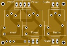
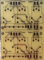
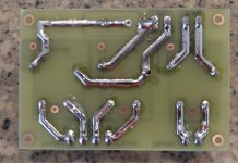
Nice! You seem to have board designing figured out! With those relays, there's no need to have the NO pin connected. Having them unhooked would give you some more room to route traces. For 120VAC you should have .080" clearance from other traces and mounting screws. Some of those traces look a little close together. Another thing I like to try to do is keep mains voltage on the bottom side of the board and control voltage on the topside, but that doesn't work as well for home etching.
My latest board design has a plug in module with those relays on it. It really cleaned up the wiring needed. I should do some experimenting with a NTC. That would cut down on even more wiring.
My latest board design has a plug in module with those relays on it. It really cleaned up the wiring needed. I should do some experimenting with a NTC. That would cut down on even more wiring.
My relays don't have the NO pin. I just added that in case someone used one that does. I didn't know about the .080" rule. Hard to imagine that 120V would arc across I actually ran the traces a little differently on the boards I etched today.
I will try the CL-60 tomorrow with a transformer and the Filter bank I will be using to check and make sure it will handle it. I keep you posted.
I will try the CL-60 tomorrow with a transformer and the Filter bank I will be using to check and make sure it will handle it. I keep you posted.
I think they are worried about dust building up in high humidity causing a short. I've got guidelines for trace widths and clearances somewhere. I'll email you a copy if I can find it.
Yes, I use an NTC on one of my Krell KSA50's. That is the entire softstart. It stays in circuit. I'm thinking for the short time it will be in circuit with this amp it should work fine. I will of course test it. I drew up some relay boards to utilize some 30A relays that I have. Hopefully these will do the trick.
Hi terry,
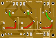
I think you don't need tracks i colored in red as they are parts of relay fonctionnality ( i have trouble to explain) If you let these tarcks output point how are connected to will ever be in "service". Tracks colored in green are not needed too as those two main input pin are internaly connected in relay.(see picture below you can see the solid metal jonction between them)
Marc
Attachments
Hi terry,
I think you don't need tracks i colored in red as they are parts of relay fonctionnality ( i have trouble to explain) If you let these tarcks output point how are connected to will ever be in "service". Tracks colored in green are not needed too as those two main input pin are internaly connected in relay.(see picture below you can see the solid metal jonction between them)
Marc
Hi Marc,
You are probably right. I have had a few different models over the years. The ones I'm using right now have 4 pins. I will have to look through my bins and see if I can round up a few more so I can check the circuit inside. The boards I etched only deal with the pins I needed. The layout I posted here was an attempt to cover more models. When I built the macro for that style relay I included all 6 pins that you might see on one. I know that it is rare that they are all used. I will do a little more research and post a more accurate layout.
Blessings, Terry
I made those observataion because i am on routing job for a simple soft start based on NTC with these type of relais.
Marc
Marc
The internal pin connections for the NO and Common are the same for all of these as well as the coil pins. The pins he's suggested are all that needs to be connected, but having all 6 pads in place will help to keep the relay connections from cracking.
The internal pin connections for the NO and Common are the same for all of these as well as the coil pins. The pins he's suggested are all that needs to be connected, but having all 6 pads in place will help to keep the relay connections from cracking.
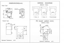
Here the pin out and diagram relay...As you can see on 6pin form => Form 6 on document, 2 main imputs are connected and that what previous picture show. For sure it' s better to have the pad even if it is connected to nothing for physical behaviour.
Attachments
The internal pin connections for the NO and Common are the same for all of these as well as the coil pins. The pins he's suggested are all that needs to be connected, but having all 6 pads in place will help to keep the relay connections from cracking.
Yes I see now. Here is a better layout. You can see that I added a few pads for the resistor(s). The narrowest holes will fit a euro terminal.
Attachments
Last edited:
Looks better! If you shift the resistor and power pads to the right, there will be more clearance from the bottom left mount screw though.
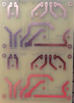
I got a chance to try the CL-60. It doesn't break sweat. It is 10ohm so some may want more resistance than that but it seems good to me. That is what I will be using. I moved the layout even further to make room for a 10W fuse if someone should choose to use one.
I'm attaching files for etching for those who may want one.
I'm attaching files for etching for those who may want one.
Attachments

- Home
- Amplifiers
- Solid State
- How to build a 21st century protection board