I've got 2 temperature sensors there with comparators, triggering the alarm 😉
I've been meaning to ask what temperature do they trigger an alarm at?
Around 90 degrees Celsius. Easy to adjust with resistors if necessary.
It may be done using analog inputs - I just decided keeping it simple at the time I designed it 🙂
It may be done using analog inputs - I just decided keeping it simple at the time I designed it 🙂
Would you have any objections to me redrawing your schematic for your great system?I've got 2 temperature sensors there with comparators, triggering the alarm 😉
Krisfr, Jeff - good list of functions, all of them are doable.
Simply depends on how far (deep, high) we want to go (dive, fly) 😀
I'm ready to support development in any area. I propose not initiating a super-duper-mega project, trying to build an inter-galactic spaceship 🙂p), but doing it gradually. We just need to arrange the hardware in a way that we will be able to move ahead without modifying it (at least for some time).
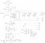
Attached is a hi-res image of the schematic (don't forget to press "eXpand" cross at the bottom left corner as soon as it opens).
Cheers,
Valery
P.S. I've got some material in microcontroller-controlled biasing - AES paper and the document Andrew (Bonsai) made available some time ago. Both are very good as a starting point for moving ahead...
Simply depends on how far (deep, high) we want to go (dive, fly) 😀
I'm ready to support development in any area. I propose not initiating a super-duper-mega project, trying to build an inter-galactic spaceship 🙂p), but doing it gradually. We just need to arrange the hardware in a way that we will be able to move ahead without modifying it (at least for some time).
Attached is a hi-res image of the schematic (don't forget to press "eXpand" cross at the bottom left corner as soon as it opens).
Cheers,
Valery
P.S. I've got some material in microcontroller-controlled biasing - AES paper and the document Andrew (Bonsai) made available some time ago. Both are very good as a starting point for moving ahead...
Attachments
Would you have any objections to me redrawing your schematic for your great system?
Not at all - please go ahead!
I've got it originally in DipTrace. I can publish my souse file - just not sure it will help as not many people use it for layout designs...
Cheers,
Valery
Could you direct us to those documents?
I think we are all on the same page. Lets keep going and I think we can make a lot happen.
I think we are all on the same page. Lets keep going and I think we can make a lot happen.
Not at all - please go ahead!
I've got it originally in DipTrace. I can publish my souse file - just not sure it will help as not many people use it for layout designs...
Cheers,
Valery
The high res helps a lot. Thanks, I see what I can do with it.
I see if I can put a LM35 on a Output lead of a Output transistor and make it track... sort of a side experiment.
It would likely be easy to adapt 2 wire sensors to your existing circuit as well. I want to fire up a heat gun and test the circuit, Just curious how long I would be heating. I think you have the pin numbers marked incorrectly on those temp sensor transistors in the schematic.
Last edited:
Is discrete device output the preferred design or IC based? I personally like ICs for driving relays. Much less clutter on the boards.
It would likely be easy to adapt 2 wire sensors to your existing circuit as well. I want to fire up a heat gun and test the circuit, Just curious how long I would be heating. I think you have the pin numbers marked incorrectly on those temp sensor transistors in the schematic.
Umm... not sure I see what you mean 🙂
They are connected as "diodes". Emitter goes to the ground, collector and base together go to comparator input...
On the MJE340s the emitter is marked with a three. I'm not sure if that is a pin making but if it is that should be pin 1.
Is discrete device output the preferred design or IC based? I personally like ICs for driving relays. Much less clutter on the boards.
I like your IC drive approach - let's go ahead with it

On the MJE340s the emitter is marked with a three. I'm not sure if that is a pin making but if it is that should be pin 1.
Ah! I see now... those numbers... well, just follow the diagram 😉
Thanks for pointing out - I will check them later today.
I like to use dip package resistor arrays for pullups/downs as well. It really helps to clean up and compact a board. they seem to be getting scarce lately though.
Ah! I see now... those numbers... well, just follow the diagram 😉
Thanks for pointing out - I will check them later today.
Just wanted to point that out for anyone redrawing the schematic. The highs and lows beside the Arduino are a little confusing as well. Whenever I get around to drawing up my version I plan to add a little truth table for the Arduino pins.

I have this for SPlan 7.0
That's fine. However, some Chinese Arduino clones, have got 2 additional pins at the top, having not 30, but 32 pins in total. My schematic and layout use this pinout for compatibility reasons - I use this 32-pin clone myself.
another control board here
I have a control board which a friend of mine developed for me. it combines fan speed control/soft start/speaker protection. it uses PIC16F819 controller (running PICbasic). fan speed is PWM controlled based on the higher of the two temperatures read (each on one channel heatsink). the temperatures are digitally read from DS18B20 temp sensors over one wire interface. the control allows for a faster warm up of classA amp since the fan is off until desired threshold temp has been reached. the PIC was chosen off the shelf and could not make use of the fan speed feedback, so the control is solely temp based.
amp on/soft start is on momentary push button and PIC delaying the second relay on PS rails.
for the speaker protection analog comparators and ICs generate DC offset alarm on which an interrupt routine in the PIC trips relays at amp outputs. this is the only part I have not tested with the real amp/music, since we included an adjust pot for both the DC trigger level (targeting 1V+-), and also one for a filter corner frequency. setting the filter so that it does not trip on loud bass, yet it is quick enough on amp failure is the tricky part which calls for a lot of fiddling and fine tuning (and I have not had the time).
there are three LEDs, for amp on, fan on, and one signalling the failure mode (overheat/Dc offset). I spent many nights with my friend troublshooting the code since there are many issues when coding at low level e.g. temp sensor not reading, or a cycle is too fast and a value is missed, etc. etc.).
I have two boards on which we fixed all the mistakes, and will need to order one more (which makes that single board very expensive). if you develop something i could use I might be interested. Otherwise i will publish mine (no secrets there) and look for anybody willing to share in the cost of my next order.
Last edited:
Very interesting. I'd like to see the schematic, if possible.
Did you use assembler for programming?
Did you use assembler for programming?
- Home
- Amplifiers
- Solid State
- How to build a 21st century protection board