Member
Joined 2009
Paid Member
Being more rare that means they automatically sound better.
Indeed, the mind is easily fooled.
I think that believing that being more rare means they automatically sound better fools the mind more than actually listening to them.......
I do not buy it that a mesh plate rectifier will make much of a difference.
I can imagine a difference for voltage amplifying tubes. Odd things happen when the electrons reach the plate.
Also by mesh plate I mean the plate in constructed from a mesh of wire. If the plate is made of metal with punched holes, then it is not a mesh plate. If you see someone calling perforated metal plate mesh plate. call them on it. Call it a perforated metal plate tube. No mesh at all.
I don't know how many on the forum actually possess mesh plate rectifiers and listen to them in A-B tests against solid plates. As with so many theoretical discussions, I think you need listening tests here. Of course all the listener bias stuff comes into play, but since we're all used to DIY and hopefully cynical about "wonderful tweaks" like oak feet and the like, and since we put money into our purchases, there's a reasonable chance that our ears are in fact telling us something.....
What I would say is that successive stages like Salas regs and Glow Tubes would tend to diminish differences from my experience. What difference there is becomes more audible with choke+cap supplies. Can be a subtle difference, but a lot of subtle differences add up in a system.
What I would say is that successive stages like Salas regs and Glow Tubes would tend to diminish differences from my experience. What difference there is becomes more audible with choke+cap supplies. Can be a subtle difference, but a lot of subtle differences add up in a system.
Last edited:
Not really from my experience. No regulator or component helped diminishing the difference between rectifiers. A regulator just regulates the voltage and might reduce ripple, but everything behind it stays audible, from the capacitor to the power transformer and mains socket.
We're talking about woven wire mesh plates here, I think
Also by mesh plate I mean the plate in constructed from a mesh of wire. If the plate is made of metal with punched holes, then it is not a mesh plate. If you see someone calling perforated metal plate mesh plate. call them on it. Call it a perforated metal plate tube. No mesh at all.
We're talking about woven wire mesh plates here, I think
Last edited:
I use -at least a bunch in different amplifiers- mesh AZ1 for decades. This tubes aging, but non of them tend to sparking.
I use ... AZ1 for decades. This tubes aging.
Do you identify that from your recollection of what the amp used to sound like years ago, to now ?
It hard to judge the general validity of posters' comments here on the 'sound' of mesh plate rectifiers (etc.). In my experience, higher efficiency speakers like horns reveal the 'sound' of amplifier, source components, and recording 'quality' far 'better' than lower efficiency speakers. So when swapping amplifier components / topology, unless we're all using similar speakers (and room?) what is it that's actually being reported, beyond individual experiences?
Is it safe to sum these experience and definitively say 'X sounds better / worse than Y' if we're all using different loudspeakers?
Is it safe to sum these experience and definitively say 'X sounds better / worse than Y' if we're all using different loudspeakers?
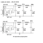
I have a power supply using 2 x AZ11 mesh. I recently tried to push up the output requirements to 280v at 140mA for 2 output tubes at 70mA each. I'm surprised at the large voltage drop at the first cap, 40uF. When I substituted 2 x AZ12 solid plate the voltages jumped up. Actually higher than shown, since the amp then drew 160mA with the existing component values. Unfortunately, while the sound is cleaner because of the higher output in the amp, the magic of the mesh plates has been lost, and the sound is flatter. So it's back to using mesh plates. I have a few AZ1 and AZ11 mesh plates. Choice seems to be:
- use 3 x AZ11 (or AZ1)
- increase the AC voltage going into the rectifier to boost the output DC voltage
With 3 rectifiers I worry about imbalance - my valve tester isn't working properly so I can't test and match them.
To optimise using 2 of AZ11/AZ1 I imagine that reducing the size of the first capacitor would help, even if it means raising the AC voltage going into them. I have CLCLC at present with 40uF first cap.
Attachments
It hard to judge the general validity of posters' comments here on the 'sound' of mesh plate rectifiers (etc.). In my experience, higher efficiency speakers like horns reveal the 'sound' of amplifier, source components, and recording 'quality' far 'better' than lower efficiency speakers. So when swapping amplifier components / topology, unless we're all using similar speakers (and room?) what is it that's actually being reported, beyond individual experiences?
Is it safe to sum these experience and definitively say 'X sounds better / worse than Y' if we're all using different loudspeakers?
anecdotes are just fine, just do not take them seriously for your stated reason...😉
If you really paralleled AZ11s (pin-to-pin), nobody knows which rectifier's half diode conduct more, than another.
If one rectifier capable conducting more current (under the same conditions) aka. has "lower impedance", it able to conducting majority of requiring DC current, so voltage drop increasing.
Usually old tube's heater resistance (at hot state) vary from tube to tube, therefore filament temperature (and amount of electrons too) also alters at the same heater voltage.
If you measure the saturating current at -for example 80V- constant anode voltage, at the same filament voltage, the "pairing" is necessary.
If you paralleled AZ11 anodes, and use it as single diode and using two tubes ("pair") as double rectifier, its IMHO the best method.
BTW PT secondary DCR also important.
I have a power supply using 2 x AZ11 mesh. I recently tried to push up the output requirements to 280v at 140mA for 2 output tubes at 70mA each. I'm surprised at the large voltage drop at the first cap, 40uF. When I substituted 2 x AZ12 solid plate the voltages jumped up. Actually higher than shown, since the amp then drew 160mA with the existing component values. Unfortunately, while the sound is cleaner because of the higher output in the amp, the magic of the mesh plates has been lost, and the sound is flatter. So it's back to using mesh plates. I have a few AZ1 and AZ11 mesh plates. Choice seems to be:
- use 3 x AZ11 (or AZ1)
- increase the AC voltage going into the rectifier to boost the output DC voltage
With 3 rectifiers I worry about imbalance - my valve tester isn't working properly so I can't test and match them.
To optimise using 2 of AZ11/AZ1 I imagine that reducing the size of the first capacitor would help, even if it means raising the AC voltage going into them. I have CLCLC at present with 40uF first cap.
you are working your tubes hard, i do not think they will live long...
rectifiers are meant to be run at a fraction of their capabilities.....
if you require larger current then get a beefier rectifier like the 5u4 or the 5ar4 and be done with it...
if you have to parallel sections, then current hogging is a possibility so it will be better to avoid it...
Attachments

Thanks euro21. I was wondering about paralleled anodes and using a single one as a diode. I should try that.
What should I do about increasing the PT DCR - put a resistor in series on one leg or two legs?
Tony: I realise that these rectifiers are working hard, but they've been on 24/7 for several years now. They've even survived sparks at switch on, which I've now stopped with a switch for the HT. From the data, I think the AZ11 is a little more robust than the AZ1 - the ratings are slightly higher. I have plenty of other rectifiers, including solid plate AZ12s which work fine. They just don't sound the same as the mesh ones.
Last edited:
resistors in series with the plates work fine....
there are curves shown here : https://frank.pocnet.net/sheets/076/a/AZ11.pdf
gives you a clue as to how to proceed...
there are curves shown here : https://frank.pocnet.net/sheets/076/a/AZ11.pdf
gives you a clue as to how to proceed...
Last edited:
i have to say those so that newbies will not think it is just fine....
those are historical tubes and who knows for how much longer we can have them?
i will not argue about that mesh plate thingy.....it is your own thing....
those are historical tubes and who knows for how much longer we can have them?
i will not argue about that mesh plate thingy.....it is your own thing....
TonyTecson said:..who knows for how much longer we can have them?
Beware, I'm collecting these from decades. 🙂
As I collected 801/801a tubes for decades ... now graphite anode 801 rare as a white crow (hungarian proverb). 😛pp
No. AZ1, AZ11, AZ21 and AZ31 are the same tubes, but with different bases. They're all successors of the venerable Telefunken RGN 1064 or Philips/Valvo G 1064. First production run for all of them featured mesh plates, later replaced by solid plates - without altering their characteristics or ratings, mind you!From the data, I think the AZ11 is a little more robust than the AZ1 - the ratings are slightly higher.
I guess you're after mesh plate rectifiers due to their more transparent sound, aren't you 😀🙄?
Best regards!
by "transparent", you mean the filaments can be seen thru the mesh plates.... 😀
have seen those too....not so impressed....
have seen those too....not so impressed....
Exactly. As the filaments clearly can be seen glowing inside the almost transparent mesh plates, an amplifier with these rectifiers sounds more transparent of course, doesn't it 🙄?
It's all about expectation bias.
Best regards!
It's all about expectation bias.
Best regards!
- Home
- Amplifiers
- Tubes / Valves
- How many rectifiers can have mesh plates?