So the data comes from a Toshiba tone generator IC. Datasheet is nowhere to be found.
Failing PCM1702s seems to be a common issue with these Clavinovas.
Failing PCM1702s seems to be a common issue with these Clavinovas.
Barring BCK at 20Fs, that is flat out wrong.Given that the prior board, which I presuming functioned correctly, utilized the PCM1702, it seems like a certainty that the incoming format was/is, Left-Justified.
Then, for a moment, forget about the PCM1794A and focus on the PCM1702. For the PCM1702 to work anything sent to it must meet needs of the PCM1702. That means 20 bit right justified data with left and right in parallel. The PCM1794A can get close to these conditions but it cannot meet them as the wordlength cannot be set to 20 bits. You will get sound but it will not be optimal.Hoping to put some new life in them.
I also notice that on your dac schematic that the PCM1794A devices have their own system clock. Doubleplusungood.
@rfbrw I acknowledge all your points but I can't go back now. The boards are built and paid for, the engineering, good and bad is done and I can't get in touch with the original engineer who did the design for me. At this point the best I can do is try to make it work. Working is still better than dead (which is what I have right now) even if the sound isn't optimal. Based on everyone's input I have identified a very logical approach to the situation.
1. set the PCM1794 to stereo mode
2 iterate through the four modes for data and see which one produces output
3. Once sound out is achieved from DAC work on the Op Amp to make sure it gets sound out.
Do I have some regrets, yes, but I can't go back. The best I can do is make v1.0 work. Plus this is how you learn.
A design for v2.0 is being considered. This is a common problem for the 90's Yamaha Clavinova. Lots of them had the PCM1702. I tried quite a few aftermarket/China stuff and they were all junk. I don't trust any of them. If anyone knows a good source, speak up.
How do you learn if you don't understand?Plus this is how you learn.
As I said earlier PCM1792 and PCM1796 (but not PCM1795) could be made to work instead of PCM1702. Unfortunately they require I2C for this so the DAC board with PCM1794 does not work.
rfbrw said:
Then, for a moment, forget about the PCM1794A and focus on the PCM1702. For the PCM1702 to work anything sent to it must meet needs of the PCM1702. That means 20 bit right justified data with left and right in parallel. The PCM1794A can get close to these conditions but it cannot meet them as the wordlength cannot be set to 20 bits. You will get sound but it will not be optimal.
As I said earlier PCM1792 and PCM1796 (but not PCM1795) could be made to work instead of PCM1702. Unfortunately they require I2C for this so the DAC board with PCM1794 does not work.
What I am hearing is one person say is, it could work (but not optimal) and another person say it won't work. Do you all understand that I am simply trying to salvage (if possible) what another engineer designed for me? Are you all saying I got screwed over by the engineer?
Then, for a moment, forget about the PCM1794A and focus on the PCM1702. For the PCM1702 to work anything sent to it must meet needs of the PCM1702. That means 20 bit right justified data with left and right in parallel. The PCM1794A can get close to these conditions but it cannot meet them as the wordlength cannot be set to 20 bits. You will get sound but it will not be optimal.
bohrok2610 said:As I said earlier PCM1792 and PCM1796 (but not PCM1795) could be made to work instead of PCM1702. Unfortunately they require I2C for this so the DAC board with PCM1794 does not work.
What I am hearing is one person say is, it could work (but not optimal) and another person say it won't work. Do you all understand that I am simply trying to salvage (if possible) what another engineer designed for me? Are you all saying I got screwed over by the engineer?
I am referring to the overall process. I acknowledge there are gaps in my knowledge. What part am I specifically missing? I have learned some things along the way such as how this DAC operates by explanations given here and studying the data sheet to help correspond what was said, to the data.How do you learn if you don't understand?
Last edited:
As I said earlier PCM1792 and PCM1796 (but not PCM1795) could be made to work instead of PCM1702. Unfortunately they require I2C for this so the DAC board with PCM1794 does not work.
Respectfully, I don't know why you would say that? This thread seems to indicate different: https://e2e.ti.com/support/audio-gr...m/165333/pcm1702u-recommended-replacement-p-n
Let's bring this back full circle. I engaged an engineer and trusted that they knew what they were doing when designing this. This was my original directions to them. "I have a circuit which utilizes a DAC chip that is end of life since 2013 or longer. Help me design a suitable replacement circuit. https://e2e.ti.com/support/audio-gr...m/165333/pcm1702u-recommended-replacement-p-n The attached file shows the DAC chip circuit. It is part of a digital piano. Engagement will be to provide circuit schematic for the replacement DAC along with any other components to be replaced." Why that engineer chose to utilize the PCM1794 I don't know. This is why I say this was all part of a learning process.
If I engage in a new design I clearly need to understand what questions to ask the engineer. IE- Setting engineering requirements
Why is this part x a suitable replacement?
What data format will it accecpt?
What is the word length?
How will your design allow for reconfiguration?
and so on...
rfbrw touched on these elements and it makes sense to me.
For the PCM1702 to work anything sent to it must meet needs of the PCM1702. That means 20 bit right justified data with left and right in parallel. The PCM1794A can get close to these conditions but it cannot meet them as the wordlength cannot be set to 20 bits. You will get sound but it will not be optimal.
Everyone here has given me food for thought. When engineering a solution you don't always get it right the first time. Sometimes we might even disagree with each other but I am here genuinely trying to learn. For all your inputs, I am appreciative.
Last edited:
Only PCM1792 & PCM1796 accept 20-bit data whereas PCM1795 doesn't. That information on TI support page is incorrect. Just look at the first page of datasheet:Respectfully, I don't know why you would say that? This thread seems to indicate different: https://e2e.ti.com/support/audio-gr...m/165333/pcm1702u-recommended-replacement-p-n
https://www.ti.com/lit/ds/symlink/pcm1792.pdf
https://www.ti.com/lit/ds/symlink/pcm1795.pdf
https://www.ti.com/lit/ds/symlink/pcm1796.pdf
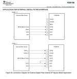
Here is how parallel data input works with PCM1796. Same information can be found from PCM1792 datasheet.
Attachments
Last edited:
Yeah, I am seeing that. And I was reviewing the conversation I had earlier with the engineer trying to "get into his head". This was the conversation he sent to me. He started by looking at the 1795 but changed to the 1794.
From the original engineer:
rfbrw said:
From the original engineer:
I reviewed the design as well as the PCM1795 . i found two things which i need to discuss:
1. the PCM1795 has builtin registers to change the settings of the DAC and can be configured over digital interface (I2C or SPI). it would have been ideal if the default settings were the same what we need but the default data format and resolution bits are different from the part we want to replace. there are two options, either i add a small microcontroller on the pcb to configure the DAC at power up or look for other alternate which wont require configuration.
2. just wanted to confirm the two DACs are configured as stereo? i see one more difference in the actual schematics and the PCM1795 or similar ICs and that is how the L and R data is received. in the original schematics the two DACs receive the same WCLK and the BCLK but different data (DACL and DACR). whereas in modern DACs, the left and right data is sent on the same data pin and the WCLK is used to tell if its L or R. i think i will have to look into detail if the PCM1795 can be used still or we might have to use two seperate DACs as in the original design. i could be wrong in understanding this and having your opinion will be helpful.
I did more research and i think the following solution will be the most suitable.
1. use DAC from same TI family but which can be configured by high and low signals to dedicated pins (instead of requiring digital communication protocol and register updates). one such IC is https://www.ti.com/lit/ds/symlink/pcm1794a-q1.pdf?ts=1659132465465&ref_url=https%3A%2F%2Fwww.ti.com%2Faudio-ic%2Fconverters%2Fdac%2Fproducts.html
2. to solve the L and R DAC data, we will have to use two DACs separately each receiving one of the two signals coming. most of modern DACs have two (stereo ) outputs but we can leave the second output unused.
rfbrw said:
I am getting a more clear picture even if I am a little slow to digest this all.forget about the PCM1794A and focus on the PCM1702. For the PCM1702 to work anything sent to it must meet needs of the PCM1702.
OK, so if I go back and look at the PCM1702. I don't see in the data sheet, a bullet point under features, for the input data. Is that inferred from the description?
20-Bit DIGITAL-TO-ANALOG CONVERTER
When reviewing the various DACs
PCM1796:
Accepts 16, 20 and 24 bit audio data
PCM Data Formats: Standard, I2S, and Left-Justified
PCM1795:
Accepts 16-, 24-, and 32-Bit Audio Data
PCM Data Formats: Standard, I2S, and Left-Justified
PCM1792:
Accepts 16, 20 and 24 bit audio data
PCM Data Formats: Standard, I2S, and Left-Justified
PCM1794:
Accepts 16, and 24 Bit Audio Data
PCM Data Formats: Standard, I2S, and Left-Justified
So basically, 1794 and 1795 are not good candidates because they don't accept 20 bit data.
What I can do now is at least configure my current 1794 to give me output (even if it is not good).
That will help confirm what data format is being sent
- Std
- I2S
- Left Justified
Attachments
I would choose digital filter bypass mode on PCM1794. That is probably the only mode that could work. But not optimally as level is low due to wrong data length and the DAC board output stage is not made for mono mode.
- Home
- Source & Line
- Digital Source
- How does this DAC work? (PCM1794)