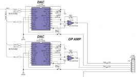
I have a PCB daughter card with a TI PCM1794 DAC. I don't have any sound output. I have this schematic for the setup. Can anyone tell me what to look for? This card was built as a replacement for the obsolete PCM1702U. I have tried validating clock inputs on pins 4,5,6 & 7. I don't measure any output on pin 17/R18 or pin 18/R19. I can only assume something is not correct on the inputs 1,2,3,10 or 11. There are a few DNP parts listed and the PCB is empty in that location. I have pictures of the clock signals that I can upload if that helps anyone.
Attachments

For clarification, is this card a commercial product, that you know worked at one time? Or is it a DIY project that has never worked?
This is "DIY" by a paid engineer. So yeah, I'm trying to troubleshoot why it's not working for the first time.
To make a long story short-
Please don't suggest going back the the engineer as they aren't around. Just hoping I can make the best of what I have to work with. I also have the original circuit that this one is replacing. I am attaching the original circuit here. The clock signals off the motherboard are fed to the daughterboard and the outputs from the daughterboard are feed back to the motherboard.
Attachments
Last edited:
Ensure that whatever is sending the data stream is formatting the samples correctly for the PCM1794A. Check the data sheet to verify what’s required. I’ve had sample data which was not correctly formatted for a given DAC produce anything from white noise, to silence. I think that the PCM1794A detects incorrect formatting and will silence the output.
Last edited:
+/-12V external supply connected to OPA1622? Might want check connections against the datasheet.
https://www.ti.com/product/OPA1622
Other things to consider is whether the 1794 is configured in a way that is compatible with 1702.
https://www.ti.com/product/OPA1622
Other things to consider is whether the 1794 is configured in a way that is compatible with 1702.
@Ken Newton, Thanks for the suggestions. I am going to closely review the data format on pins 11 & 12.
I think that is probably the best thing to look at right now. I see according to the datasheet that if you configure the DAC for mono mode then you must look at the chart on page 17 to set the data format. https://www.ti.com/lit/ds/symlink/pcm1794.pdf According to the schematic both DACs were "wired" the same for data format (and that can't be). because one DAC is left and the other DAC is right.
Your suggestion makes good logical sense. Are you pretty sure the PCM1702U uses left justified data? (Therefore, it's logical to setup the PCM1794 in the same mode as the original DAC). So, it looks like I may need to reconfigure some of the resistors involved with pins 11 & 12.
My knowledge on DACs is growing. I only started by learning what is current vs voltage modes.
@kevinkr. Thanks for the suggestion but I don't think I am even getting output from the DAC right new. I'm going to concentrate my efforts on the DAC. Once I can confirm some signal output from the DAC I can start to look at the OPA1622. 🙂
Agreed! That is the path I am heading down.Other things to consider is whether the 1794 is configured in a way that is compatible with 1702.
According to you DAC schematic PCM1794 is configured to Left-justified, stereo, slow rolloff. I would expect DAC output to be at IOUTL+/IOUTL- (pins 25, 26). Do you see anything at those pins?
Left justified - yes, at least according to the schematic. Also, I am still not positive if the 1794 should be left justified (I haven't heard an affirmative response on that yet). It would be according to whatever the PCM1702U is and we set the 1794 to match it.
Stero- Well according to resistor positions I'd agree but notice that the engineer didn't use the stereo function on the output to the opamp. So I think that means CHSL should be set to 1. IE move resistor at R3 to R2 and R24 to R23. Would you agree?
For now, that is what I have done. I have moved resistors and placed them at R2 and R23. DNP R3/24. (This is a change from how the board was shipped to me originally) After making that change I don't see any output on pin 17 & 18 (measured on R18, R19, R39 & R40)
Last edited:
I forgot to mention the PCM1794 is a current output DAC and the OPA1622 is configured for voltage amplification R16/R37 and R17/R38 really should be installed. (<100 ohms - I used 10 - 20 ohm resistors in my last one.) I recommend reading the PCM1794 data sheet and application notes as I am more than a decade out from the last time I used this DAC IC.
I would probably also hold the DAC chip in reset until it powers up and then pull it high?
I would probably also hold the DAC chip in reset until it powers up and then pull it high?
OK, so place 100 ohm for each of those resistors, got it. Seems you replied while I was modifying my post (SORRY). Yeah, I still need to get some output from the DAC to work with. (See my previous post) Does everything I describe seem to look correct?
And yes, I have been going over the data sheet to figure out what "should" be.
And yes, I have been going over the data sheet to figure out what "should" be.
The PCM1794A can be set to a number of sample data formats. Right-justified(RJ), I2S and Left-justified(LJ). The RJ format further requires setting to either 16-bit, or 24-bit sample data depth. LJ and I2S self-adjust to fit the input data width. Which format is correct for your board depends on the format in which the data is being sent. That is the format master, while the DAC is the format slave. If the sending format is not known, or easily determined you simply will have to step through setting the DAC though the different formats until you stumble across the correct one. Since that would require hacking the PCB some, hopefully, the sending format can be determined without much trouble. Most likely, the format is either I2S or Left-justified, in that order.
Assuming this is the problem with the board, which it may not be, music will play when you hit the correct format. The DAC should be reset after each format change, which will happen you power down the board, then power it back up after each change in the mode setting pins. Also, pay attention to pins ‘MONO’ and ‘CHSL’, which programs the DACs to function in mono (one per channel), and each in its correct left/right data position. PCM1794A formats are set via four hardware-mode pins, specified in Table-3 on page-16, of the data sheet. The format relevant pages are 12 through 16.
Assuming this is the problem with the board, which it may not be, music will play when you hit the correct format. The DAC should be reset after each format change, which will happen you power down the board, then power it back up after each change in the mode setting pins. Also, pay attention to pins ‘MONO’ and ‘CHSL’, which programs the DACs to function in mono (one per channel), and each in its correct left/right data position. PCM1794A formats are set via four hardware-mode pins, specified in Table-3 on page-16, of the data sheet. The format relevant pages are 12 through 16.
Last edited:
Thanks Ken, this is making a lot of sense as I have been reading the data sheet and your explanation. As mentioned in my previous post I already changed the DAC to mono by moving CHSL resistor. So I think now I just need to iterate through the formats until I get one that gives me output from the DAC.
At present:

At present:

Given that the prior board, which I presuming functioned correctly, utilized the PCM1702, it seems like a certainty that the incoming format was/is, Left-Justified.
But it would not have been serialized nor would it have needed MCLK. There is also a possibility, if not probability, it came off a digital filter which means word clock need not have a 50:50 m/s ratio and bit clock need not be continuous. Not to mention the oversampling itself.
The DAC schematic does not support mono mode properly. In PCM1794 mono mode one output channel is inverted so that IOUT+/- pins of both channels can be in parallel. IOUTR+ with IOUTL- and IOUTR- with IOUTL+. So IMO stereo is the correct mode in this case and I still suggest to measure what's on IOUTL+/- (pins 25, 26).
A single PCM1792/PCM1795/PCM1796 would have been a better choice as they can accept separate DATAL and DATAR input. Albeit only through I2C settings.
Last edited:
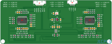
From the motherboard, with the exception of SCK. I hand wired some jumpers . Attached is an approximate representation of the PCB daughterboard. The engineer did provide several DNP parts locations/pads so that the DAC can be configured. My mistake when starting this process was thinking it was "all correct and should just work". I am learning a lot. Thanks to everyone for the input!Where is the audio data coming from ?
FWIW: If anyone is wondering, the system in question is a Yamaha Clavinova CVP 207. They are still a fairly nice instrument despite it's age. The service manual with complete schematics can be found all over the interwebs.
| PCM1702 | PCM1794 |
| QCLK IC28&29 P2 | BCK U3&U4 P6 |
| WCLK IC28&29 P7 | LRCK U3&U4 P4 |
| DACL IC28 P1 | DATA U3 P5 |
| DACR IC29 P1 | DATA U4 P5 |
| SCK from Xtal on daughterboard |
Attachments
OK, wasn't aware of that. I can go back and reconfigure the DAC for stereo mode. I'll be sure to check pins 25 & 26 at that time.The DAC schematic does not support mono mode properly. In PCM1794 mono mode one output channel is inverted so that IOUT+/- pins of both channels can be in parallel. IOUTR+ with IOUTL- and IOUTR- with IOUTL+. So IMO stereo is the correct mode in this case and I still suggest to measure what's on IOUTL+/- (pins 25, 26).
The first half of that statement is definitely true. I did have one MB that was functional but lost left channel after a minute or two. If I swapped DAC positions the problem moved. So yes, definitely bad DAC. I couldn't find anything definitive about formats (unless I missed something) but it is likely a good assumptionGiven that the prior board, which I presuming functioned correctly, utilized the PCM1702, it seems like a certainty that the incoming format was/is, Left-Justified.
I do have two units to fix. The 2nd one had no sound at all but if I swapped in the other MB from the1st unit, I got sound, so I had to assume both DACs gone on the 2nd unit. (Though it could be something else but that seems the most probable cause.)
- Home
- Source & Line
- Digital Source
- How does this DAC work? (PCM1794)