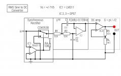
I've come up with another idea for a rectifier that can be built with parts I have lying about. I haven't tried it yet, but I seen something similar before and it was capable of wide bandwidth. What concerns me is control signal breakthrough in the analog switch upsetting the measurements.
See attached:
I realize the CD4053B is not the best analog switch IC but at the moment I can't buy any new parts. ( We spent a small fortune getting the kids new clothes for school, which started this week! )
Gordon.
See attached:
I realize the CD4053B is not the best analog switch IC but at the moment I can't buy any new parts. ( We spent a small fortune getting the kids new clothes for school, which started this week! )
Gordon.
Attachments
Last edited:
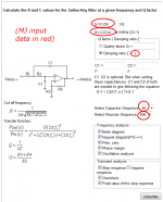
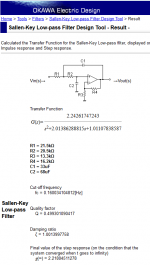
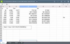
Maybe you didn't realize that you can build Sallen-Key filters with any DC gain (greater than one) that you desire. Here's one whose DC gain is PI/SQRT(2), coughed up by a free LPF calculator webpage on the internet.
The DC gain appears in the output data, twice. First it is the ratio of the constant term in the numerator, divided by the constant term in the denominator:
In both cases, the DC gain pops out to be exactly the number you wanted. With one fewer opamp.
The DC gain appears in the output data, twice. First it is the ratio of the constant term in the numerator, divided by the constant term in the denominator:
- DC gain = 2.242617 / 1.011078 = 2.218045
In both cases, the DC gain pops out to be exactly the number you wanted. With one fewer opamp.
Attachments
Thanks Mark that will be useful. I am looking again at power supply cleanup options. I started a thread to discuss one circuit I found, here:
26db PS noise reduction circuit
Gordon.
26db PS noise reduction circuit
Gordon.
Last edited:
high gains are not recommended with Sallen-Key - the sensitivity of the filter Q to component tolerances rises very quickly with gain in the filter
high gains are not recommended with Sallen-Key - the sensitivity of the filter Q to component tolerances rises very quickly with gain in the filter
Would a gain of pi/√2, 2.22 approx be considered a high gain in this context?
more critical in XO or EQ applications, especially in higher order filters where individual biquad sections may have higher Q
missing the Q of a single 2nd order Butterworth biquad in a hi or low pass to change fc droop/peaking a dB or 2 may not be a problem
missing the Q of a single 2nd order Butterworth biquad in a hi or low pass to change fc droop/peaking a dB or 2 may not be a problem
So what's the dQ/dGain, at Gain=1.00 and also at Gain=2.22, for a 2nd order lowpass with (zeta=1, Q=0.5), at 1 radian/second, as found in this thread? Is the change in dQ/dGain large enough to require a design change, from (10% capacitors + 1% resistors), to tighter tolerance, more expensive parts? Or is this one of those "slightly bigger but insignificant in practice" factoids that are enjoyable to pontificate, but beneficial to neglect?missing the Q of a single 2nd order Butterworth biquad in a hi or low pass to change fc droop/peaking a dB or 2 may not be a problem
https://www.google.com/#q=sallen+key+biquad+sensitivity
1st ref:
1st ref:
– In Fact the Sensitivity of Q to K is Quite High for High Q Stages
• The Sensitivity is Proportional to Q & Proportional to the Square-Root of the
Larger Capacitor Divided by the Smaller Capacitor
• These Two Factors Combined Make The Sensitivity Proportional to Q^2
Last edited:
err should have linked it: http://www.ti.com/lit/ml/sprp524/sprp524.pdf
well worth reading further down than you can follow the math if that's a problem for the summary statements, example circuits, plots
well worth reading further down than you can follow the math if that's a problem for the summary statements, example circuits, plots
Last edited:
After a lot of trial and error I have gotten the 50Hz noise problem under control.
Both of the power supplies I was using had several volts ac on their outputs with respect to mains earth, I assume the result of capacitive coupling ( it was at a high Z )
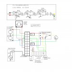
I have devised a scheme that has yielded the best results so far. I have included a diagram of all interconnections as well as the amplifier that I ended up using.
I tried Udos idea of direct input to the virtual earth of the first amplifier, but this didn't work so well in practice. Instead I reconfigured stage 1 as a simple differential amplifier, using 4 hand picked 1K resistors ( within 0.2% )
Along with the re_arrangement of the grounding the 50 Hz problem has been minimized.
I tried the setup with a 50.23M test resistor and there was way too much capacitive coupling at 5 & 10 KHz. This was corrected by: (i) Rearranging input and output signal wires away from one another. (ii) Using one of the connections on the terminal block that the CCS is constructed on as a screen, connected to earth. This worked very well, see diagram to see how it was done, it is marked "Sc"
If we are going to attempt to measure any CCS claimed to have Z = 1 Gohm, I think perhaps an instrumentation amplifier and a noise reduction circuit for the CCS power supply ( the variable one ) will be in order. My simple differential amp only has around 40db CMRR at 1Khz.
Should be able to do some measurements soon!
Both of the power supplies I was using had several volts ac on their outputs with respect to mains earth, I assume the result of capacitive coupling ( it was at a high Z )
I have devised a scheme that has yielded the best results so far. I have included a diagram of all interconnections as well as the amplifier that I ended up using.
I tried Udos idea of direct input to the virtual earth of the first amplifier, but this didn't work so well in practice. Instead I reconfigured stage 1 as a simple differential amplifier, using 4 hand picked 1K resistors ( within 0.2% )
Along with the re_arrangement of the grounding the 50 Hz problem has been minimized.
I tried the setup with a 50.23M test resistor and there was way too much capacitive coupling at 5 & 10 KHz. This was corrected by: (i) Rearranging input and output signal wires away from one another. (ii) Using one of the connections on the terminal block that the CCS is constructed on as a screen, connected to earth. This worked very well, see diagram to see how it was done, it is marked "Sc"
If we are going to attempt to measure any CCS claimed to have Z = 1 Gohm, I think perhaps an instrumentation amplifier and a noise reduction circuit for the CCS power supply ( the variable one ) will be in order. My simple differential amp only has around 40db CMRR at 1Khz.
Should be able to do some measurements soon!
Attachments
Last edited:
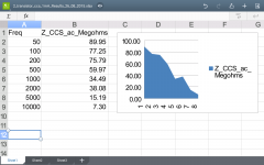
OFirst results from new setup:
CCS supply = 30 Vdc
Vccs(DC) = 27.5 Vdc
I_ccs_(DC) = 1.0mA
Results attached.
I have made some more measurements with a 1 transistor and LED ccs and got some unexpected results.
Will post these as soon as I have compiled the data.
CCS supply = 30 Vdc
Vccs(DC) = 27.5 Vdc
I_ccs_(DC) = 1.0mA
Results attached.
I have made some more measurements with a 1 transistor and LED ccs and got some unexpected results.
Will post these as soon as I have compiled the data.
Attachments
Last edited:
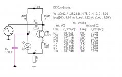
The results for the 1 transistor and led based current source are unexpected, as you will see. I have rechecked everything several times yet the results are the same.
I'm not sure if this circuit is exposing a flaw in the measurement setup.
The led is a low current (2mA) red led. The transistor is the same bc547b used in the 2 transistor circuit.
Can someone run a simulation of this to see is these results are in any way credible.
See attached:
I'm not sure if this circuit is exposing a flaw in the measurement setup.
The led is a low current (2mA) red led. The transistor is the same bc547b used in the 2 transistor circuit.
Can someone run a simulation of this to see is these results are in any way credible.
See attached:
Attachments
Last edited:
This looks very fishy:
might be that you have a transistor having a minimal Early effect, and that the topology in itself is exceptional, but the increase of impedance with frequency is definitely unrealistic: I see no mechanism capable of that, except an insufficient value of a bypassing cap, like C2, but this is certainly not the case here.
Talking of C2, why do you connect it that way, instead of simply bypassing the LED?
Maybe it's OK, but I wouldn't count this as certain without going into the maths of the circuit.
The way the whole setup is arranged looks questionable too, unless it is proven otherwise: what you measure is certainly not the impedance of the CCS: it is something else, because of Ri and Rbias. It might be that they are approximately the same thing, but this would need to be demonstrated. I cannot decide instinctively one way or the other, but it makes me uncomfortable and I would feel the need to dig somewhat deeper to make an informed decision
Basically, anything that departs from the root measurement of the impedance is potentially suspicious, especially at this level of accuracy.
Apply Kirchhoff's current law: The current through the 1k resistor is equal to the
collector current if the current through Rbias and through C2 is zero.
Rbias should be 100k for less than 1% error and C2 should be small (or connected to the
emitter).
The -3 dB frequecy is too low for the 2-transistor CCS. Simulation gives 2MOhm for the 1-transistor CCS (-3dB @ 100kHz).
collector current if the current through Rbias and through C2 is zero.
Rbias should be 100k for less than 1% error and C2 should be small (or connected to the
emitter).
The -3 dB frequecy is too low for the 2-transistor CCS. Simulation gives 2MOhm for the 1-transistor CCS (-3dB @ 100kHz).
Apply Kirchhoff's current law: The current through the 1k resistor is equal to the
collector current if the current through Rbias and through C2 is zero.
Rbias should be 100k for less than 1% error and C2 should be small (or connected to the
emitter).
I didn't think there would be a problem with the current in the led branch as it's DC, and the DC component is blocked in the amplifier or are you concerned with ac coupling from the power rail? Perhaps Rbias could be replaced with a jfet?
The -3 dB frequecy is too low for the 2-transistor CCS. Simulation gives 2MOhm for the 1-transistor CCS (-3dB @ 100kHz).
I thought the -3db point was too low also, I'm not sure what has gone wrong here. The results for the 1 transistor CCS are most odd.
Elvee, do you think measuring impedance with a current sensing resistor in the ground leg of the CCS is inherently flawed? Should the measurement be taken in the collector path?
There is AC current in the LED branch because point D
is modulated by the collector AC current and
point +VS is modulated too due to finite power supply impedance.
This error is small if Rbias is larger than 100x Ri and C2 is connected to D.
if you keep the AC current in Rbias << Ic then there is no problem with measuring
the current at Ri (apply Kirchhoff current law).
A jfet current source in place of the 18k resistor would surely be better, as it would have a pretty high impedance at ac. Tomorrow I will try this, as well as connecting C2 across the led as Udo and Elvee have suggested.
Goodnight.
Goodnight.
- Status
- Not open for further replies.
- Home
- Amplifiers
- Solid State
- How do you calculate impedance of a current source?