Member
Joined 2009
Paid Member
ostripper said:That is exactly what I plan, the only difference is the big (but not much ,according to mr. cordell) , capacitances at the gates of the IRF's. The standard supersym with a modified Vbe , has slightly higher distortion but a different FFT response. This seems to be the subthreshold region of the MOSFET as compared to the abrupt on/off nature of the BJT. Combined with the lack of Gm doubling , a very good sounding, high current OP stage might be possible (likely).
I have isolated the switching distortion in the amp for both OPS's and "like" what I see from the MOSFET's.
I am going to try it both ways , CFP and EF.
OS
I'm not sure why you feel BJTs have abrupt on/off, I thought they were actually slow to turn off. Also I thought all devices suffer from variable Gm, even MOSFETs ?
I'm particularly interested in CFP after hearing the improvement when it's used in the LTP. But there's not very much written about how well CFP o/p helps with cross-over distortion. I suspect that there are problems with BJT CFP in Class B because of the slow BJT turn off (no charge-suck-out cap) so either you use the CFP in Class A (LTP, VAS, drivers) or you have to use BJT-MOSFET. I think this is the reason you are seeing better results.
How did you 'isolate' the switching distortion - is it a simple matter to compare the output biassed into Class A with Class AB ? how did you eliminate non-linear loading of the VAS as a contributor ?
I have been looking at some of Wavebourn's output designs - nice use of CFP there too.
CFP has a very ugly turn off transition when used in Class AB.
The slave device which does the heay lifting is used in common source/emitter, giving phase shift issues which make it relatively intolerant of reactive loads compared to the DEF. In practice bias adjustment is very tetchy.
OTOH it is very linear, has low Zout, and very little large signal compression because the master device is operating at near constant current and therefore has very small Vbe variation. If the switching transitions could be controlled better, this would lead to far lower odd order distortion. Yep, in Class A these output stages are the best.....
The Radford/Bailey Class AB collaboration of the sixties produced the ZD50, which is an interesting variation on a CFP; a triple, with a double rail for the final driver. It's also a diamond buffer, as the pre-driver on the positive rail is pnp, an interesting design.
Hugh
Member
Joined 2009
Paid Member
Thanks Hugh, some words of wisdom, as usual.
So for CFP output, we need a non-switching ClassAB so that each CFP pair is operating in essentially a ClassA-type mode.
That brings me back to my playing with the Blomley output, simple in it's principle of dividing the current, buffering it and then re-combining it. A current-mirror with current-gain.
Do you have something from Radford/Bailey you can post - perhaps into this thread as an example of 'complexity' 😉
Member
Joined 2009
Paid Member
tinitus said:I built my first speakers at 12-13 years, together with a school mate
Though it is very interesting to see fullrange drivers get such revival
I have sold my 3way speakers and decided to use the money on a pair of 18" woofers and a couple of 2" Beyma CD mounted in Azura horn
Wow, you have been a life-long DIY'er. There's never been a good substitute for experience.
I love full-range, my first (and only) DIY speakers are Fostex 127E's in an Onken style box. I don't know if there is a revival, but the Full Range forum is fairly active. After I built mine, I was gob-smacked by their clarity. But they don't have enough oomph at the low end so a 2-way with a full-range is on my planning board.
I've never had 3-ways, seems like an example of 'complex' to me, whereas full range with an assisting woofer is my idea of 'optimal simplicity'.
Hi,
some nice features for a simplified 60's creation.
I like the input filtering, the Pi output filtering, the diamond drivers, the cascoded VAS, the CFP that is then darlingtoned. Where did they get complementary output devices in the 60's?
All that with just 12 transistors.
How much simplification has taken place?
How well did it perform, cf. it's peers and today?

The Radford design, like their tube designs, is revolutionary for its time. It represents the flowering of all Bailey's ideas, and the adventurous spirit of Radford, who were technical leaders.
I'm an admirer, I really am.
It would not be that much more complex in real life; there would be lots of decoupling caps, additional driver power supplies stapled over the power rails, elaborate current sources for the predrivers and LTP, and cascode voltage references. None of this is too hard.
Cheers,
Hugh
Member
Joined 2009
Paid Member
I like it, meets my desire for low parts count i.e. simple and it looks like a topology that feels comfortable in it's own shoes. I don't understand the feedback loop, seems to have a strong frequency dependency with only a capacitor to gnd from the inverting node. Is this why there is no Cdom, the design is old enough that VAS transistors had enough internal Cdom to remain stable and the feedback loop maintains a low shunt resistance at higher frequencies to roll-off the response ?
I like the CPF output, I feel drawn to this type of output. It seems a natural way to combine devices.
But that man Carlos, he's planted a seed. Despite our protestations. I am starting to find myself getting slowly but surely less interested in looking further at a topology that I am now more familiar with and want something new. I need to find something new to add to what is now familiar and yet keep it simple. I don't want to add more devices, that's not the direction for me.
Hi,
follow the NFB route all the way to the ground.
It goes through a resistor then a capacitor and finally another resistor.
The order of the last two C+R component does not matter in normal feedback.
Radford have also added a bit of +ve feedback using that extra resistor going up to the +IN line.
It bootstraps the input impedance and requires the reversal of those two components.
I'll guess the input impedance was raised to mimic the typical impedances of valve gear that dominated good High Fidelity at the time.
Member
Joined 2009
Paid Member
By Bigun - I need to find something new to add to what is now familiar and yet keep it simple. I don't want to add more devices, that's not the direction for me.
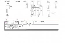
here is something that is part radford , part QSC , part folded. I admit I "stole it" from the VSOP (syn08) , but it works ... VERY GOOD. I drove a triple and a pair of IRF's with it. It also "bucks the trend" as far as sound goes for a full symmetrical amp .
OS
Attachments
Member
Joined 2009
Paid Member
Lots of interesting goodies in there 😉
Perhaps I should take a look at some symmetrical designs, that would be new for me. At least a look.
Perhaps I should take a look at some symmetrical designs, that would be new for me. At least a look.
- Status
- Not open for further replies.
- Home
- Amplifiers
- Solid State
- How complex to make an amplifier ? (lighthearted)