badman said:
I'm not sure that's the case. More mass is one thing, when you layer it.... one layer heats the next more directly than it can any cooling feature. This is why I stated the preference for single-layer....
Single layer, long coil in long cap?
/Peter
There are quite a few issues when it comes to creating good sound. We're talking specifically about motors here so we wont' focus on cone resonance, spider resonance, etc. If you look through the Klippel Non-Linear distortion poster you can see a good overview of everything. It's a BIG image so I won't post it in the thread, but here is the link:
http://www.klippel.de/download/Nonlin/Klippel_nonlinearity_poster.jpg
Here is the summary of which symptoms are caused by which non-linearities.
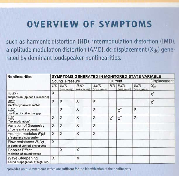
We will focus on both the BL(X) and Le(x) and Le(i). Bl(X) is the change in Bl with respect to excursion. You can see that all of the issues with Bl non-linearity are in the realm of sound pressure. This leads to compression of quick bursts when the coil has to move large distances. There just simply isn't as much motor strength to move the coil at high excursions so some output is lost. To get to a point where you could approach an audible effect from this the BL would have to drop to less than 70% of the rest value. Up to the rated Xmax this is essentially an inaudible effect. If you're using a driver within its excursion limits it isn't much of a factor.
Lets look at Le(x) though which is inductance with respect to position. Looking at the chart we see that this has effect in both sound pressure and current. This is a much more critical issue and keeping inductance linear is a very serious issue. A coil is essentially an inductor. The steel pole is the iron core. As the coil moves inward and outward the steel core is essentially changing. This changes the inductance from a high value on the inward stroke to a lower value on the outward stroke as it becomes more of an aircore inductor. How much it changes depends on the length of the pole, overall Le of the coil itself, etc. As the Le is changed, the impedance curve greatly changes and as a result you have the change in current applied to the driver at various points.
Here is a comparison of the old HE15 TC made for us back some years ago. This was a very high inductance driver. At rest and on inward stroke the Le was about 6mH and you can see this response in the Blue curve. As the coil comes fully forward the Le drops greatly. The blue curve is response on the inward stroke and red is response on the outward stroke. I think it is quite clear that there is effect over the entire frequency range. Now imagine a driver like this trying to play 1KHz where you have nearly 20dB difference in the response from inward to outward stroke. This is the "unique symptom" noted on the chart for IMD created in the current domain.
The next graph is one I did for the car audio guys showing the IDMAX 12(top graph) vs an AV12X(bottom graph). The IDMAX is not an overly high inductance driver and could be comparable to many hifi type woofers out there. You can see that there is again an effect on current even from 50-100hz as inductance changes. However when you take a very low inductance driver like the AV12X, the effect s very minimal up until well over 1KHz.

Then we need to look at the effect of Le(i) which is flux modulation. This is probably the biggest issue in distortion. All the symmetry that is worked to get in the flux field doesn't mean much if the flux isn't fixed in the gap. As the coil is energized it becomes an electromagnet. The more current applied, the stronger it's own field becomes. As this field moves through the gap it moves the permanent the flux field around. This isn't an effect seen in a modeled response curve, but is very clear if you do an FEA model showing the coils effects on the permanent field at various positions.
The key for a motor is to get the Bl(x), Le(x), and Le(i) to all be limited to inaudible levels. The attempts at linearzing Bl often create even more issues with Le(x) or Le(i). Trading one distortion that only has effect on sound pressure for greater issues that cause both sound pressure and current domain issues is not the right philosophy.
Back to the original post about overhung drivers. Bl(x) only becomes an issue only after Xmax(Bl 70% of rest value) has been surpassed. If you need to play louder without it becoming an issue simply use more or bigger drivers and keep them in the right operating range and it is no issue. Where an overhung typically has the most issue with Le(x) and Le(i) so those issues need to be addressed. You need to keep inductance the same throughout the excursion limits to lower Le(x) and keep the flux from moving in the gap to take care of Le(i). Our link on the Lambda motor explains our solution which is the full copper sleeve over the pole. This cuts overall inductance to a very small fraction of what it would be and makes the coil act nearly as an air core inductor. Any change in inductance then is so minor that it only affects the current domain many octaves above the usable range of the driver. This essentially eliminates any issue with inductance change based on position. At the same time this permanently mounted highly conductive copper sleeve eliminates flux modulation. Any flux movement now creates large currents (Eddy Currents) that short themselves out. The magnetic flux lines are electrically shorted to their original location and cannot move. The full copper sleeve over the entire pole is the most effective way to handle both Le(x) and Le(i)
You can read more on the Lambda motor here if you wish
http://www.aespeakers.com/Lambda001-1.php
John
http://www.klippel.de/download/Nonlin/Klippel_nonlinearity_poster.jpg
Here is the summary of which symptoms are caused by which non-linearities.
We will focus on both the BL(X) and Le(x) and Le(i). Bl(X) is the change in Bl with respect to excursion. You can see that all of the issues with Bl non-linearity are in the realm of sound pressure. This leads to compression of quick bursts when the coil has to move large distances. There just simply isn't as much motor strength to move the coil at high excursions so some output is lost. To get to a point where you could approach an audible effect from this the BL would have to drop to less than 70% of the rest value. Up to the rated Xmax this is essentially an inaudible effect. If you're using a driver within its excursion limits it isn't much of a factor.
Lets look at Le(x) though which is inductance with respect to position. Looking at the chart we see that this has effect in both sound pressure and current. This is a much more critical issue and keeping inductance linear is a very serious issue. A coil is essentially an inductor. The steel pole is the iron core. As the coil moves inward and outward the steel core is essentially changing. This changes the inductance from a high value on the inward stroke to a lower value on the outward stroke as it becomes more of an aircore inductor. How much it changes depends on the length of the pole, overall Le of the coil itself, etc. As the Le is changed, the impedance curve greatly changes and as a result you have the change in current applied to the driver at various points.
Here is a comparison of the old HE15 TC made for us back some years ago. This was a very high inductance driver. At rest and on inward stroke the Le was about 6mH and you can see this response in the Blue curve. As the coil comes fully forward the Le drops greatly. The blue curve is response on the inward stroke and red is response on the outward stroke. I think it is quite clear that there is effect over the entire frequency range. Now imagine a driver like this trying to play 1KHz where you have nearly 20dB difference in the response from inward to outward stroke. This is the "unique symptom" noted on the chart for IMD created in the current domain.
The next graph is one I did for the car audio guys showing the IDMAX 12(top graph) vs an AV12X(bottom graph). The IDMAX is not an overly high inductance driver and could be comparable to many hifi type woofers out there. You can see that there is again an effect on current even from 50-100hz as inductance changes. However when you take a very low inductance driver like the AV12X, the effect s very minimal up until well over 1KHz.
Then we need to look at the effect of Le(i) which is flux modulation. This is probably the biggest issue in distortion. All the symmetry that is worked to get in the flux field doesn't mean much if the flux isn't fixed in the gap. As the coil is energized it becomes an electromagnet. The more current applied, the stronger it's own field becomes. As this field moves through the gap it moves the permanent the flux field around. This isn't an effect seen in a modeled response curve, but is very clear if you do an FEA model showing the coils effects on the permanent field at various positions.
The key for a motor is to get the Bl(x), Le(x), and Le(i) to all be limited to inaudible levels. The attempts at linearzing Bl often create even more issues with Le(x) or Le(i). Trading one distortion that only has effect on sound pressure for greater issues that cause both sound pressure and current domain issues is not the right philosophy.
Back to the original post about overhung drivers. Bl(x) only becomes an issue only after Xmax(Bl 70% of rest value) has been surpassed. If you need to play louder without it becoming an issue simply use more or bigger drivers and keep them in the right operating range and it is no issue. Where an overhung typically has the most issue with Le(x) and Le(i) so those issues need to be addressed. You need to keep inductance the same throughout the excursion limits to lower Le(x) and keep the flux from moving in the gap to take care of Le(i). Our link on the Lambda motor explains our solution which is the full copper sleeve over the pole. This cuts overall inductance to a very small fraction of what it would be and makes the coil act nearly as an air core inductor. Any change in inductance then is so minor that it only affects the current domain many octaves above the usable range of the driver. This essentially eliminates any issue with inductance change based on position. At the same time this permanently mounted highly conductive copper sleeve eliminates flux modulation. Any flux movement now creates large currents (Eddy Currents) that short themselves out. The magnetic flux lines are electrically shorted to their original location and cannot move. The full copper sleeve over the entire pole is the most effective way to handle both Le(x) and Le(i)
You can read more on the Lambda motor here if you wish
http://www.aespeakers.com/Lambda001-1.php
John
John
A very good review. I would agree that Le(x,i) variation is the more audible problem than Bl(x,i) variation and that some form of flux modulation and Le control is essential. I also agree that if Bl(x) effects are audible then you are simply using the driver beyond the excursion that it was designed for and need either a bigger driver or more of them.
Where I think that we might differ is on the extremes that one needs to go to to reduce these effects below audibility. You appear to take the "maximum is always enough" approach, but I prefer the "most cost effective" one. Either way we agree on the goal, just maybe not on the price.
Wow, those graphs are amazing! I'd never have expected changes on that order of magnitude. Any better idea of the Le of the ID driver?
This level of amplitude differential explains a lot of why better drivers sound the way they do. AlNiCo motors being less susceptible to flux modulation is a bigger plus here than one might have suspected. Underhung, likewise, makes more sense than ever, here.
JBL has gone to great lengths to reduce flux modulation in their better motors, using a high degree of shaping in the undercut polepiece to ensure that it remains saturated. Many drivers use an undercut polepiece, It would seem that as much of a shorting path underneath this as possible would be desirable.
And, it's important to note, that this certainly points to the 'bigger is better' school, and horns fit into that. Your filters, active or passive, can't address this issue, the only solution lies in motor design and upscaling the size of the driver (and limiting excursion)
ALNICO is a better magnet in regards to flux modulation if no other means of control are used. ALNICO is not a good electrical conductor however, so while it is "better" if no shorting ring is used, a shorting ring of copper, etc. easily defeats any advantage. ALNICO shines with thermal changes however - its like zero!
From all that I know "bigger IS better". People just don't want to hear that because bigger is a lower WAF. Can't have everything I suppose. My solution - hide the speakers and WAF goes away - you can't complai about the size of what you can't see.
From all that I know "bigger IS better". People just don't want to hear that because bigger is a lower WAF. Can't have everything I suppose. My solution - hide the speakers and WAF goes away - you can't complai about the size of what you can't see.
JBL silver plated the polepiece in the LE8T (which is also underhung), which REALLY gives the best of all worlds 🙂
Naturally we'd like to see the plating be a thick ring rather than a modest plating, but it's still good.
Naturally we'd like to see the plating be a thick ring rather than a modest plating, but it's still good.
badman said:JBL silver plated the polepiece in the LE8T (which is also underhung), which REALLY gives the best of all worlds 🙂
Naturally we'd like to see the plating be a thick ring rather than a modest plating, but it's still good.
There was an AES paper a few years ago that talks about the ratio of thickness of the shorting ring and conductivity vs its effectiveness at lower frequencies. Basically the thicker it is, the lower in frequency it has effect. The more conductive it is, the more effect it has at those frequencies. Thin plating on a tweeter pole could be effective or thin plating on a fullrange driver could improve the upper most frequencies, but wouldn't have a full bandwidth benefit.
John
I did some work on plating as a shorting ring. Turns out that the conductivity is lower than expected for a thin layer and only begins to approach the theoretical values as the layer got thicker. From a physics point of view this is completely logical. Plating works, but only if the layer is thick enough. Most plating is only a several atoms thick. It takes a lot of atoms to get the metal structure up to what it needs to be to get the lowest resistance.
One other advantage is that AlNiCo motors seemed to default to T-shaped polepieces, increasing saturation and reducing flux modulation.
Agreed their low level of conductivity is not terribly useful, but better than nothing, and there's, IIRC, also better thermal conductivity which is also useful. the big iron pots in some aren't a bad heatsink either 🙂
Agreed their low level of conductivity is not terribly useful, but better than nothing, and there's, IIRC, also better thermal conductivity which is also useful. the big iron pots in some aren't a bad heatsink either 🙂
badman said:
I'm not sure that's the case. More mass is one thing, when you layer it.... one layer heats the next more directly than it can any cooling feature. This is why I stated the preference for single-layer....
Problem with a single layer coil (like most edgewound pro stuff) is you have to solder the lead out wires to the usually aluminum voice coil wire and ain't too many people in the world that can do that, and even then its still a solder joint in a high heat environment.
Re: overhung vs underhung
For woofers/subwoofers I prefer super extended poles like described here covered with a thick sleeve of copper. With a typical coil overhang you don't see as much of the B loss from the thick copper in the gap as the B is now so spread out (and there is wire to still be in its path)
When I designed the Lambda motor I got so much copper in the gap to drop the inductance from ~5mH down to less than 0.5mH but the B(l) didn't really drop that much with the longer voice coils we used.
The copper of course then also became the first step in a serious heatsink process to keep the Re as constant as possible. A win win in my book.
spkrguru said:In standard overhung motors, there is more steel below the top-plate than above the top-plate making 2 problems.
a) Induction differences as the coil goes in and out of the pole.
b) Non linear magnet field from the top to the bottom of the coil.
There are 2 ways to make good overhung voice-coils in standard magnet sandwiches.
2) If the pole-piece is extended to 2x the Xmax, there is good linearity. This is great for sub-woofers because the L is high and there is a lot of extra steel to help cool the coil.
For woofers/subwoofers I prefer super extended poles like described here covered with a thick sleeve of copper. With a typical coil overhang you don't see as much of the B loss from the thick copper in the gap as the B is now so spread out (and there is wire to still be in its path)
When I designed the Lambda motor I got so much copper in the gap to drop the inductance from ~5mH down to less than 0.5mH but the B(l) didn't really drop that much with the longer voice coils we used.
The copper of course then also became the first step in a serious heatsink process to keep the Re as constant as possible. A win win in my book.
- Status
- Not open for further replies.
- Home
- Loudspeakers
- Multi-Way
- How can an overhung voice coil produce good sound?