Bgt said:
pcb for T-NETs:
http://www.grotel.nl/photo/TNET2.jpg
After listening the whole day, comparing amps....well...still no magic. Checked, double checked with a scope.....no magic
 .
.The plus side is the small physical size and the low ESR, like the Vishays. Price wise....horrible. The Vishays can be bought for something like € 7,- pp ex VAT(at 25 pieces) at the main Vishay representative.

Bgt said:
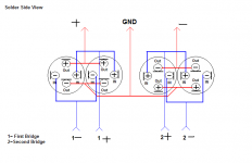
Hi, Thanks for the diagram.
I can see how it works and I'd dare say.... less than optimal.... but then again you're all about the cross talk, so it looks like you're going for dual mono so to speak.
An idea that I had, had I more bridge rectifiers, would be to use one per rail. There you have your better speration and you're using the caps a little better.
Withing reason of cost though, we'll stick to two rectifiers, keep them isolated from one another. Additionally it lets you parallel your caps, which is a big improvement.
Regardless fo a few days worth of break in time, you should hear the magic instantly. I'd suspect something with the ground or the aluminum plate, that sort of thing can really make it or break it. Why I like to use wire, it's easy to swap around just see how it reacts.
I'll keep you posted on my latest triple T-net per rail supply, but because you're not hearing magic..... something is wrong without how it's configured, I can promise you that.
Regards,
Chris
classd4sure said:
Hi, Thanks for the diagram.
I can see how it works and I'd dare say.... less than optimal.... but then again you're all about the cross talk, so it looks like you're going for dual mono so to speak.
An idea that I had, had I more bridge rectifiers, would be to use one per rail. There you have your better speration and you're using the caps a little better.
Withing reason of cost though, we'll stick to two rectifiers, keep them isolated from one another. Additionally it lets you parallel your caps, which is a big improvement.
Regardless fo a few days worth of break in time, you should hear the magic instantly. I'd suspect something with the ground or the aluminum plate, that sort of thing can really make it or break it. Why I like to use wire, it's easy to swap around just see how it reacts.
I'll keep you posted on my latest triple T-net per rail supply, but because you're not hearing magic..... something is wrong without how it's configured, I can promise you that.
Regards,
Chris
Chris, I am all open ears. I value your opinion highly so if there is a good id........bring m on.
Bert
Hey Bert, Was that a steel or brass bolt? If it's a steel one, Well, don't know what to tell ya.
Ray
Ray
Chris,
Just wondering....before you had the Jensens what caps. did you have? Your experience with the Jensens is a nice 1. You also have the FRED rect. Maybe that's doing something too. Can you remember how the sound was without Jensens, Freds? Did you exchange them at the same time or modded it first with the Jensens or the other way around?
Cheers Bert
Bgt said:Chris,
I took the bolt out of the toroid. So used none......no magic.
Haha, thank you I could always use a laugh.
Actually there's some theory behind that for it possibly making a difference. The induced flux going through the center of the toroidal core will induce eddy currents to flow in the mounting bolt. Will they bend the flux lines to an audible degree? I find that extremely unlikely. Will the bolt begin to mechanically vibrate from eddy current? Find that highly unlikely too. We're concerned with 60Hz, not 6Mhz.
If rice makes people in China fart.. will I hear it on over my amp?
Somewhere you have to draw the line, unfortunatly for most when that line drawn defines their sales pitch there's usually no known limits and that can be very dangerous.
Anyway at least in this case it cost you nothing to try, caused no collateral damage, and now you can laugh at anyone with a 20$ brass bolt when you say "where'd you get your amp from, it's so shiny".
Anyway, I'm not sure if you actually wired your PSU as you've drawn it, I will therefore assume you've done exactly that and base my comments accordingly.
You have a huge loop going from one cap "supply" common point, to the other cap common point. The output side of that loop is loaded by the amp's power ground, while the input side of that is loaded/driven by the centertap. Basically this will be a point of infliction, and a nasty one since it will have the ability to vary the common point semi dependant on load given the wire parasitics.
I would consider the more conventional method of wiring them with a dual secondary, dual bridge rectifier, parallell 2 jensen's per rail, in which way you'll benefit from their lower ESR and ESL, even more, and your rails + ground will be fully isolated from the secondaries.
That should get you the magic. Now it also matters where you add your wires.... I think I've been thinking about latelly and plan on demonstrating some theory with a working circuit, I'll be happy to write up a paper on it when complete.....
Originally I used Cerfine wiht a generic IC bridge of about 25amps, with the most straight forward wiring going. Here's a tip for you. __________THE ONLY WAY______ to get full benefit of the inherent filtering capabilities of the T-neworks is the dual bridge/isolated rails method. If you do that you'll hear the magic and it's the kind of instant jaw dropping "wow".
This, sadly, is why when I upgraded to the first set of BHC T-networks which were donated to me by Lars Clausen, under the bet that I would hear no audible difference, I already knew how to make full use of them and immediatly upgraded to twin rectifiers. "Wow". Otherwise, I doubt I would have heard much different at all.
Please let me know if this helps.
Attachments
classd4sure said:You have a huge loop going from one cap "supply" common point, to the other cap common point. The output side of that loop is loaded by the amp's power ground, while the input side of that is loaded/driven by the centertap. Basically this will be a point of infliction, and a nasty one since it will have the ability to vary the common point semi dependant on load given the wire parasitics.
Chris, what loop do you mean? If you mean the 1 common 0V point to the other , there is some hefty thick solid wired soldered on the PCB track so that the 0V lines are really low ohmic. With a scope I measure nothing there.
Besides that the whole PCB is 12.5 cm long and 75mm wide. So tracks are short. Don't forget I have the 10 ohm resistors in the input shield/ground so you don't have any false currents running there from the 0V ground lines.
As per using separate windings, I would need 4 of them, so 2 toroids. So thats not an option for me. The housing is too small.
Have to try this with a bigger housing and 2 toroids.
But thats another day/month. I still want proof if it makes a difference!!!! Otherwise bye bye T-Nets.(Not the dustbin ofcourse)
For now it just is a kind of waste really.
Not sure but I think you misunderstand. The big expensive way which I think would offer the best of both worlds would in fact be two 4 bridge rectifiers (two extra secondaries an even more expensive "option".
In thi scase, do that same job, parallel your caps kind of like my diagram shows, the cap common point is your only ground. You dont' need any new parts at all just some different wiring..... provided you do have dual secondaries.
In thi scase, do that same job, parallel your caps kind of like my diagram shows, the cap common point is your only ground. You dont' need any new parts at all just some different wiring..... provided you do have dual secondaries.
classd4sure said:Not sure but I think you misunderstand. The big expensive way which I think would offer the best of both worlds would in fact be two 4 bridge rectifiers (two extra secondaries an even more expensive "option".
In thi scase, do that same job, parallel your caps kind of like my diagram shows, the cap common point is your only ground. You dont' need any new parts at all just some different wiring..... provided you do have dual secondaries.
Chris...explain? How to use 4 bridges on a single toroid with 2 separate secundary windings? Yes, my toroids has 2 sep. windings on the sec. side.
I got it, U want a single power supply for 2 channels. That will ruin my soundstage. Thats going back to the stone age.
I will try to build a 2 toroid 4 bridge psu for testing these caps. If thats the only way to test these suckers?
But that wont be till next week/month.
I hope sergio(coldamp) is sending me the SMPS's soon! That will be nice to test. Small and powerful. At least it will fit in any small amp. Wonder how sep. will be?
Chris, thx.
Cheers Bert
You have secondary, two paralleled bridges, with a bank of positive caps off each one (that is don't parallel the two positive cap banks, they become parallel at the bridge rectifiers where the current splits).
Same for the negative rail. You'll then have 4 common points to tie together...... ooooooooor maybe to leave float, and connect their shields direct?
Really this way each rail has full isolation from secondaries via paralleled bridge rectifiers.
That does require at least two more rectifiers though, if you can't do that, at least get ride of the centrap arrangment, parallel your caps and wire it up like my diagram, I promise you instant T network magic.
Once you've got that way you very well may want to revisite your ground lifts on the input too. But we'll worry about it later.
Regards,
Chris
Bert,
Please try separate windings to the input of each bridge. At the moment you have created a centre tapped transformer by joining two of the secondaries together.
Also, and not wishing to be unkind, the layout of your amp is not optimal. It is tight but I am sure it could be improved. Your power
supply wiring is unnecessarily close to your signal wiring, but to change it will mean changing the position of your amplifier boards,
Transformer and filter caps.
IME once this is done you can do things like use unshielded input wiring, which usually sounds better. Place the boards properly and you can have the input wiring as short as 30-60 millimetres.
As it stands I believe your layout may well be choking the ultimate sound quality you can achieve,
Rob.
So, you parallel the caps, and drop the centertap? you parallel from the Plus lead to Minus lead of the rectifier, with both minuses of each cap going to the minus of the rectifier? Or do you do a back to back on the caps, plus and minus together and just parallel the caps off the rectifier?
Ray
Ray
Robert F said:Bert,
Please try separate windings to the input of each bridge. At the moment you have created a centre tapped transformer by joining two of the secondaries together.
Also, and not wishing to be unkind, the layout of your amp is not optimal. It is tight but I am sure it could be improved. Your power
supply wiring is unnecessarily close to your signal wiring, but to change it will mean changing the position of your amplifier boards,
Transformer and filter caps.
IME once this is done you can do things like use unshielded input wiring, which usually sounds better. Place the boards properly and you can have the input wiring as short as 30-60 millimetres.
As it stands I believe your layout may well be choking the ultimate sound quality you can achieve,
Rob.
I can agree about the layout but again it can often be a difficult matter of compromise... size of case Vs size of everything Vs' .... The modules are very robust in this way, but it could definatly be cleaned up.
First things first though, dual non-centertap secondaries with // 4 poles.....magic will begin to appear. Then do you what you have to do to ditch the ground lift. You'll get a slap of holography you'll never forget.
classd4sure said:Then do you what you have to do to ditch the ground lift. You'll get a slap of holography you'll never forget.
What do you mean by groundlift?🙁
The funny thing is I 've used a 2 toroids 4 bridge design in the 80's but it did nothing special. It was not the key to super wide soundstage......that was the grounding of the system. Once you have that figured out it does not matter how you feed the psu's of both amps. Thats why I abbandoned the 2 toroid setup completely. Didn't find any benefit from it. Maybe with the T-NETS it does?
Hi Bert,
Well, from what I gather, is just a rearangement of the power supply circuit. Just hook each bridge to each secondary. The only ground required here is at the caps. no center tap at all needed.
Ray
Well, from what I gather, is just a rearangement of the power supply circuit. Just hook each bridge to each secondary. The only ground required here is at the caps. no center tap at all needed.
Ray
I know it is a small housing but I've changed the wiring a 100 times, it is quit irrelavant how you layout the wiring. By ear you cannot hear the difference and with a scope...... 3 Db max. But who cares at -90DB@15Khz.Robert F said:Also, and not wishing to be unkind, the layout of your amp is not optimal. It is tight but I am sure it could be improved. Your power supply wiring is unnecessarily close to your signal wiring, but to change it will mean changing the position of your amplifier boards,Transformer and filter caps.As it stands I believe your layout may well be choking the ultimate sound quality you can achieve,
I did nummerous measurements and it is that good for such a small housing that I am happy with it. It is spacious.
Comparing it with a bigger housing shows that it does not compromise. Days and days of A/B switching shows that you would would need 10k speakers to hear the difference.
There is a limit to what 1 can spend.
- Status
- Not open for further replies.
- Home
- Amplifiers
- Class D
- Hotrodding the UCD modules