Thanks for the replies 🙂
I have to solve this before I start to mod the modules.
I see you propose slightly different approachs.
Have you looked at Rane's recommendation? I could not say that I heard a change (for better or worse) when I did it.
I did it before and didn't help. Now, I will pass the advice because of:
1) safety.
2) I'm waiting for a DIY "technical balanced isolation transformer" that should be well served by maintaining earthing:
http://www.equitech.com/articles/articles.html
http://www.equitech.com/articles/widescreen.html
UCD400 are mono.
So, is the "T-piece" grounded by the suspension bolts?
I fear that by floating the "cap's common plate" from chassis this could affect VDC simetry. It still would be connected to "UCD's PS ground pin", though, and through "T-piece", perhaps, to chassis?
Ah! so many permutations possible. If I lift some wire from ground it may still be acting as antenna, safe if I completelly desolder it. 😡
I'll "measure twice and cut once" 😀
Thanks a lot for your kind and helpful interest 🙂
I wish you luck.
Mauricio
I have to solve this before I start to mod the modules.
I see you propose slightly different approachs.
I have XLR. I would try both, connected and disconnected to signal input and chassis. I have zero noise at idle with my ear "inside" the coaxial with my present setup.FOR SURE connect input signal ground to input (RCA, or XLR).
Have you looked at Rane's recommendation? I could not say that I heard a change (for better or worse) when I did it.
Also, if the other chassis ground connection you mention is a three prong ground..... loose it.
I did it before and didn't help. Now, I will pass the advice because of:
1) safety.
2) I'm waiting for a DIY "technical balanced isolation transformer" that should be well served by maintaining earthing:
http://www.equitech.com/articles/articles.html
http://www.equitech.com/articles/widescreen.html
I've also never tried floating the supply ground with a center tap, but I imagine you could and it shouldn't hurt to try. Leave the CT connected to the plate common point, keep both module power grounds connected at the very same spot on that plate, disconnected the plate from the chassis so it that it floats from it. I thought you floated your pin 1 signal ground, not connected it to chassis?
UCD400 are mono.
So, is the "T-piece" grounded by the suspension bolts?
I fear that by floating the "cap's common plate" from chassis this could affect VDC simetry. It still would be connected to "UCD's PS ground pin", though, and through "T-piece", perhaps, to chassis?
Ah! so many permutations possible. If I lift some wire from ground it may still be acting as antenna, safe if I completelly desolder it. 😡
I'll "measure twice and cut once" 😀
Thanks a lot for your kind and helpful interest 🙂
I wish you luck.
Mauricio
The T sinks should have a low impedance bypass to ground on the module so it shouldn't be a concern if you screw it to the case.
Play it safe, make the changes and Vdc symmetry with the modules disconnected. With the Center tap connected to the cap neutral plate though, it should stay in check, you might see a volt or so difference, which I've found acceptable, and drops to being equal rails with even a small load attached.
While your modules are out and disconnected, make sure the screws to the T-sink are snug and the bypass caps (easy to find they connect to the screws) are properly soldered. No point doing this if that's not right.
Keep us posted of the results.
Chris
I have recently got my 400 modules. They sounded normal during initial testing. However, when viewed over a scope, I found the traces "hairy" although the shape of the curve appeared to be normal too, like this one of 10KHz square wave taken at an output of about 1W on 8 Ohm load :
http://i12.photobucket.com/albums/a250/ThomasC2/ucd10KHz.jpg
A 300VA transformer with two 15000uf Elna caps have been used for each channel. Noise was so low that it actually could not be heard.
I have been trying hard to finish reading this thread but believe it will take a few more days. In the meantime, any advice will be highly appreciated.
Thomas
ThomasC said:I have recently got my 400 modules. They sounded normal during initial testing. However, when viewed over a scope, I found the traces "hairy" although the shape of the curve appeared to be normal too, like this one of 10KHz square wave taken at an output of about 1W on 8 Ohm load :
http://i12.photobucket.com/albums/a250/ThomasC2/ucd10KHz.jpg
A 300VA transformer with two 15000uf Elna caps have been used for each channel. Noise was so low that it actually could not be heard.
I have been trying hard to finish reading this thread but believe it will take a few more days. In the meantime, any advice will be highly appreciated.
Thomas
Thanks for the nice pictures. For me everything looks normal, this is the HF residue driving on top of the 10kHz signal.
You should do this measurement on other Class-D products and please show them to us.... 😉
Jan-Peter
Jan-Peter,
Thanks a lot for the quick advice. I'd like to (do it to some other class D amps too) but unfortunately I don't have them at this moment. Anyhow, I feel very comfortable now. Will work on the case from now on.
Regards,
Thomas
Thanks a lot for the quick advice. I'd like to (do it to some other class D amps too) but unfortunately I don't have them at this moment. Anyhow, I feel very comfortable now. Will work on the case from now on.
Regards,
Thomas
I measured a few output caps
Hello all,
I measured the influence of a few different output caps on the output signal of the UcD.
I used an almost standard UcD400 and measured the output signal of the UcD with a pc-based scope (50Mhz 12 bit sampling, 0.8V range) without applying any input signal.
I tried 3 different output caps.
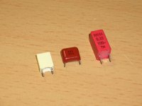
1. the standard white cap
2. the read cap that comes installed on the newer modules I believe, I think that is a Panasonic ECQV series cap
3. 2 WIMA 330nF 100V MKP2 (polypropylene) in parrallel
Attached is a picture showing all 3 caps
I will show measurements in the next post
Hello all,
I measured the influence of a few different output caps on the output signal of the UcD.
I used an almost standard UcD400 and measured the output signal of the UcD with a pc-based scope (50Mhz 12 bit sampling, 0.8V range) without applying any input signal.
I tried 3 different output caps.
1. the standard white cap
2. the read cap that comes installed on the newer modules I believe, I think that is a Panasonic ECQV series cap
3. 2 WIMA 330nF 100V MKP2 (polypropylene) in parrallel
Attached is a picture showing all 3 caps
I will show measurements in the next post
Attachments
Nice one ghemink😎 look forward to reading your results.
I'm going to try these too in my UCD180 http://uk.farnell.com/jsp/endecaSearch/partDetail.jsp?SKU=3891057&N=401
I'm going to try these too in my UCD180 http://uk.farnell.com/jsp/endecaSearch/partDetail.jsp?SKU=3891057&N=401
Re: I measured a few output caps
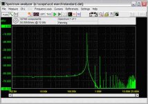
The measurements attached show an FFT using 32768 samples for all 3 caps.
It can be seen that the panasonic cap performs slightly better than the standard white cap as the high frequencies above 3 Mhz are slightly better attenuated.
The 2 WIMA caps perform even better in that respect as the HF components between 3 and 10Mhz are below -80dBV and the components above 10Mhz are about 6dB lower as for the other caps.
Further interesting to note is that the peaks at about 400kHz, 1.2Mhz, 2Mhz and 2.8Mhz are higher in amplitude than for the other caps. This may look bad but is actually better. I calculated that the signal at those frequency components is actually closer to the expected value when you assume a square wave of 400kHz going into the LC filter that drops off with 12dB/Oct. The fact that the other caps show lower values at those frequencies indicates that there is more jitter with the other caps, thus a somewhat varying oscillation frequency resulting in the peaks to be smeared out a bit so that they look lower. So it looks like the WIMA caps behave more like the ideal cap, also nice that the filter out more rubbish above 3Mhz.
I have not listened to these caps yet 🙂. I plan to experiment with the 470uF caps and replace them with others and measure the effect in a similar way, maybe measure the voltage over those 470uF caps.
Best regards
Gertjan
ghemink said:Hello all,
I measured the influence of a few different output caps on the output signal of the UcD.
I used an almost standard UcD400 and measured the output signal of the UcD with a pc-based scope (50Mhz 12 bit sampling, 0.8V range) without applying any input signal.
I tried 3 different output caps.
1. the standard white cap
2. the red cap that comes installed on the newer modules I believe, I think that is a Panasonic ECQV series cap
3. 2 WIMA 330nF 100V MKP2 (polypropylene) in parrallel
Attached is a picture showing all 3 caps
I will show measurements in the next post
The measurements attached show an FFT using 32768 samples for all 3 caps.
It can be seen that the panasonic cap performs slightly better than the standard white cap as the high frequencies above 3 Mhz are slightly better attenuated.
The 2 WIMA caps perform even better in that respect as the HF components between 3 and 10Mhz are below -80dBV and the components above 10Mhz are about 6dB lower as for the other caps.
Further interesting to note is that the peaks at about 400kHz, 1.2Mhz, 2Mhz and 2.8Mhz are higher in amplitude than for the other caps. This may look bad but is actually better. I calculated that the signal at those frequency components is actually closer to the expected value when you assume a square wave of 400kHz going into the LC filter that drops off with 12dB/Oct. The fact that the other caps show lower values at those frequencies indicates that there is more jitter with the other caps, thus a somewhat varying oscillation frequency resulting in the peaks to be smeared out a bit so that they look lower. So it looks like the WIMA caps behave more like the ideal cap, also nice that the filter out more rubbish above 3Mhz.
I have not listened to these caps yet 🙂. I plan to experiment with the 470uF caps and replace them with others and measure the effect in a similar way, maybe measure the voltage over those 470uF caps.
Best regards
Gertjan
Attachments
Re: Re: I measured a few output caps
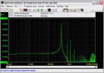
This is with the panasonic
ghemink said:
The measurements attached show an FFT using 32768 samples for all 3 caps.
It can be seen that the panasonic cap performs slightly better than the standard white cap as the high frequencies above 3 Mhz are slightly better attenuated.
The 2 WIMA caps perform even better in that respect as the HF components between 3 and 10Mhz are below -80dBV and the components above 10Mhz are about 6dB lower as for the other caps.
Further interesting to note is that the peaks at about 400kHz, 1.2Mhz, 2Mhz and 2.8Mhz are higher in amplitude than for the other caps. This may look bad but is actually better. I calculated that the signal at those frequency components is actually closer to the expected value when you assume a square wave of 400kHz going into the LC filter that drops off with 12dB/Oct. The fact that the other caps show lower values at those frequencies indicates that there is more jitter with the other caps, thus a somewhat varying oscillation frequency resulting in the peaks to be smeared out a bit so that they look lower. So it looks like the WIMA caps behave more like the ideal cap, also nice that the filter out more rubbish above 3Mhz.
I have not listened to these caps yet 🙂. I plan to experiment with the 470uF caps and replace them with others and measure the effect in a similar way, maybe measure the voltage over those 470uF caps.
Best regards
Gertjan
This is with the panasonic
Attachments
Re: Re: Re: I measured a few output caps
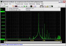
This is with the two WIMA caps.
ghemink said:
This is with the panasonic
This is with the two WIMA caps.
Attachments
Hi Gertjan,
Excellent work, thanks for sharing.
Do you suppose the Wima perform better and are more stable in frequency due to having two in parallel and thus lower ESR? Also how were they mounted, one on top and one on the bottom?
I'm sorry if I missed it but what was the input signal, or was this done at idle? Might be interesting to step the input/amplitude. Maybe we'd get to see the microphonic effect begin to appear with the stacked film or something?
What 470nF are you going to try?
Thanks,
Chris
Originally posted by "classd4sure" Chris
Do you suppose the Wima perform better and are more stable in frequency due to having two in parallel and thus lower ESR? Also how were they mounted, one on top and one on the bottom?
I'm sorry if I missed it but what was the input signal, or was this done at idle? Might be interesting to step the input/amplitude. Maybe we'd get to see the microphonic effect begin to appear with the stacked film or something?
It takes much care in measurement setup to get good "apples-to-apples" comparisons. To keep the noise floor out of the picture, the basic measurement must be very clean. This is probably best done using a 'scope tip jack (facilitates a "zero" length ground lead) soldered in-circuit at the measurement point and a common mode choke installed on the probe cable (wrap it several times through a high perm ferrite toroid). Also, the fft time window probably must be carefully realigned for each measurement as the UcDs operating frequency will vary slightly with variations in the output capacitor's value and ESR (this could explain some of the subtle differences in the harmonic ratios and "noise" floor prior to the first peak, etc.).
Just a thought. -- analogspiceman
Sorry to interrup this interesting talk. 
Quick report about my HF noise on UCD180. I found the time to address it and one of the little 22uF/50V caps was dammaged: it had brownish material on bottom. I changed it for a 4.7uF BG-N that I had on hand and this channel has now good HF performance. The other unmoded channel has tolerable distortion. I could hear the wonderful performance of Tchaikovsky's violin concerto by David Oistrach without getting sick. 🙂
No one seem to have suffered from this failure and the other (visible) caps look good so I guess it's bad luck. Anyway, my iron is hot and nervous and I want to swap more caps.
Please help me to identifie the caps wich are good to be changed.
What do you use for AC coupling and low voltage PS decoupling?
I have here some Elna Starget 22uF/50V wich usually make the sound colorful and warm but are not too transparent. Are they OK for those tasks?
![URL]](/community/proxy.php?image=http%3A%2F%2F%5BURL%3Dhttp%3A%2F%2Fimageshack.us%5D%5BIMGDEAD%5Dhttp%3A%2F%2Fimg505.imageshack.us%2Fimg505%2F7817%2Fsacnucd180caps5ml.jpg%5B%2FIMGDEAD%5D%5B%2FURL%5D&hash=81eaf6fde1702a1d571ca6783e0cf91b)
The one that failed is the red cap on bottom/left, with an arrow and a "1".
Is the bootstrap the lonely, solid blue cap? (on the figure, that is)
This image was imported from the parallel thread and has markings for outboard opamp PS (for the brave among us 😀 ).
Many thanks for helping with UCD "nomenklatur" 🙂
Mauricio
Quick report about my HF noise on UCD180. I found the time to address it and one of the little 22uF/50V caps was dammaged: it had brownish material on bottom. I changed it for a 4.7uF BG-N that I had on hand and this channel has now good HF performance. The other unmoded channel has tolerable distortion. I could hear the wonderful performance of Tchaikovsky's violin concerto by David Oistrach without getting sick. 🙂
No one seem to have suffered from this failure and the other (visible) caps look good so I guess it's bad luck. Anyway, my iron is hot and nervous and I want to swap more caps.
Please help me to identifie the caps wich are good to be changed.
What do you use for AC coupling and low voltage PS decoupling?
I have here some Elna Starget 22uF/50V wich usually make the sound colorful and warm but are not too transparent. Are they OK for those tasks?
The one that failed is the red cap on bottom/left, with an arrow and a "1".
Is the bootstrap the lonely, solid blue cap? (on the figure, that is)
This image was imported from the parallel thread and has markings for outboard opamp PS (for the brave among us 😀 ).
Many thanks for helping with UCD "nomenklatur" 🙂
Mauricio
maxlorenz said:Sorry to interrup this interesting talk.
Quick report about my HF noise on UCD180. I found the time to address it and one of the little 22uF/50V caps was dammaged: it had brownish material on bottom. I changed it for a 4.7uF BG-N that I had on hand and this channel has now good HF performance. The other unmoded channel has tolerable distortion. I could hear the wonderful performance of Tchaikovsky's violin concerto by David Oistrach without getting sick. 🙂
No one seem to have suffered from this failure and the other (visible) caps look good so I guess it's bad luck. Anyway, my iron is hot and nervous and I want to swap more caps.
Please help me to identifie the caps wich are good to be changed.
What do you use for AC coupling and low voltage PS decoupling?
I have here some Elna Starget 22uF/50V wich usually make the sound colorful and warm but are not too transparent. Are they OK for those tasks?
The one that failed is the red cap on bottom/left, with an arrow and a "1".
Is the bootstrap the lonely, solid blue cap? (on the figure, that is)
This image was imported from the parallel thread and has markings for outboard opamp PS (for the brave among us 😀 ).
Many thanks for helping with UCD "nomenklatur" 🙂
Mauricio
Brownish material you say, sure it's not just some left over resin? Rather odd for that cap to have a problem I'd think, it's just the AC coupling cap, hardly put to work at all, but, if you say it helped..
So yeah the two red ones are the coupling caps, get ride of them or upgrade them (you've seen the warnings etc)
Yes the blue cap is the bootstrap cap.
Black ones need to be high ESR, I haven't changed mine.
Blue stripped is the filter cap, upgrade it! Black stripped are the high voltage local supply/decoupling caps, take your best shot with those, they can change the sound a good deal.
Here is a shot of the Wima's on my v5 boards. My new v6 boards have the red Panasonic caps so I will be able to compare them with the Wima's. Also installed a separate PS and regulators for the Op-amps late last Friday. Only about 50 Hrs. on them so far but the sound is very good. I will post more on this later.
Attachments

classd4sure said:Hi Gertjan,
Excellent work, thanks for sharing.
Do you suppose the Wima perform better and are more stable in frequency due to having two in parallel and thus lower ESR? Also how were they mounted, one on top and one on the bottom?
I'm sorry if I missed it but what was the input signal, or was this done at idle? Might be interesting to step the input/amplitude. Maybe we'd get to see the microphonic effect begin to appear with the stacked film or something?
What 470nF are you going to try?
Thanks,
Chris
Hi Chris,
The two in parallel may actually be a factor, this should lower the inductance and the caps itself have a lower loss, and thus a lower ESR already.
There was no input signal as I wanted to have the FFT as clean as possible, not modulated by an input signal.
With the 470nF, I mean 470uF for the power supply decoupling caps. Thinking of trying panasonic FC 680uF/100V but also have some other caps lying around.
Best regards
Gertjan
analogspiceman said:
It takes much care in measurement setup to get good "apples-to-apples" comparisons. To keep the noise floor out of the picture, the basic measurement must be very clean. This is probably best done using a 'scope tip jack (facilitates a "zero" length ground lead) soldered in-circuit at the measurement point and a common mode choke installed on the probe cable (wrap it several times through a high perm ferrite toroid). Also, the fft time window probably must be carefully realigned for each measurement as the UcDs operating frequency will vary slightly with variations in the output capacitor's value and ESR (this could explain some of the subtle differences in the harmonic ratios and "noise" floor prior to the first peak, etc.).
Just a thought. -- analogspiceman
Hi spiceman,
I know it is easy to make a worthless measurement. I connected about 30cm speaker cable to the UcD module. I used an 8Ohm dummy load and hooked up the oscilloscope probe at the end of that speaker cable. So the GND loop of the probe was quite far away from the UcD module itself. I also used a ferrite core on the scope cable to suppress common mode noise and I connected only one probe, so using only 1 measurement channel. Since the FFT window I used was long (32768 samples at 50Mhz sample rate) I think I do not have to worry too much about the accuracy related to that.
I have actually made a home made BNC cable ending with two twisted wires (for GND and signal) to be soldered directly to the PCB to minimize the loops that can pick up noise. I actually have used that already to measure the signal over the 470uF power supply decoupling caps, using it with a common mode suppressing ferrite core as well. I could nicely measure the waveform over the cap. Want to experiment with different caps later.
Best regards
Gertjan
Mike2 said:Here is a shot of the Wima's on my v5 boards. My new v6 boards have the red Panasonic caps so I will be able to compare them with the Wima's. Also installed a separate PS and regulators for the Op-amps late last Friday. Only about 50 Hrs. on them so far but the sound is very good. I will post more on this later.
Are those the same WIMA`s as I`m using?
Gertjan
- Status
- Not open for further replies.
- Home
- Amplifiers
- Class D
- Hotrodding the UCD modules