Needing to reduce R2-2 R2-3 that much to get the current up would imply the bd's have a rather lower than usual beta, not even quite 20. If this is the case then the odd behavior may be the opamp hitting it's current limit.
Needing to reduce R2-2 R2-3 that much to get the current up would imply the bd's have a rather lower than usual beta, not even quite 20. If this is the case then the odd behavior may be the opamp hitting it's current limit.
They tested OK on the meter (both 100+) of course the hFE maybe potentially a lot less at the current they're being operated at, I will try taking some measurements at the operating current to see if you are right. Thanks again for your input.
Gordon.
Latest update:
The hFE of the bd139's are good, well above 100 at the currents used in the circuit. The current going into the base of the lower bd139 is around 1mA, the reason that I chose 2 x 750R, is in keeping with the rule of thumb that the bias chain should run at 10 to 20 times the base current, with the remainder of this current (90_95%) going into the collector of the "error amplifier" transistor, that is the BC550 in this circuit.
(BTW, I learned this rule of thumb from the the Elliot Sound Products website, they have tons of educational material relating to audio electronics.
This is the page about current sources:
Current Sources, Sinks and Mirrors in Audio
I have determined two issues;
The CCS was "ringing" when the negative peaks went above a certain level, this has been corrected by the inclusion of a 150n capacitor between the base of the bc550 and ground, this creates a low pass filter, in conjunction with the 1k base resistor with a cutoff frequency of ~ 1 kHz, so considerable attenuation at ultrasonic frequencies.
The "freak out" at clipping was found to be opamp related, for some reason the opamp was saturating during clipping periods, however the circuit worked OK with a humble 741! I tried an LF351, but it oscillated at nearly 1 MHz!!
A TL071 exhibited the same problem as the ne5534.
I'm suspecting that the opamps are having too much demanded of their output stages, I'm going to try an emitter follower at the output of the opamp, to bolster its drive capability, if this fails to rectify the problem, I'm going to look at a discrete voltage amplification solution.
Have been doing a crash course in transistor amplifier design, last night I mastered the hybrid pi model and Millers thereom!
Have figured out what was happening with the opamps.
I was attempting to push the output beyond 8 volts peak ( not peak to peak ) and of course with a 1 amp current source, the maximum swing into an 8R load is only 8 volts. The opamp tried to "correct" this by swinging all the way to its negative rail ( it did, I viewed it on my 'scope ) I'm still not sure why it worked OK with the 741, that's still a mystery to me.
I am taking time out to look at designing a discrete voltage amplification stage. I have dug out my electronics books which were stowed away in a cupboard.
I am probably sticking with the driver / output stage but ultimately with it operating at a higher bias current in the output devices.
I have decided to scrap this whole approach and have dedicated my efforts to developing my electronics knowledge such that I can build something good with discrete solid state parts.
To this end I started a thread regarding the impedance of current sources. It has turned into quite a lengthy and interesting discussion, involving some actual practical experiments:
http://www.diyaudio.com/forums/solid-state/272044-how-do-you-calculate-impedance-current-source.html
To this end I started a thread regarding the impedance of current sources. It has turned into quite a lengthy and interesting discussion, involving some actual practical experiments:
http://www.diyaudio.com/forums/solid-state/272044-how-do-you-calculate-impedance-current-source.html
Something that I forgot to mention before deserting this thread for good, is to thank everyone for their helpful advice and suggestions, you have motivated me to better my knowledge of electronics and for that I am truly grateful.
Gordon.
Gordon.
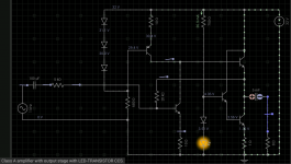
Have taken the liberty of ressurecting this thread. Inspired by some of my earlier lessons from various members, I have come up with a draft for a similar class A amplifier. It is intended that this would be preceded with a preamp stage as it has a low voltage gain in itself. Comments and recommendations are of course encouraged and welcomed.
Gordon.
Gordon.
Attachments
Well it should work, but, how well....
I should be able to run a better simulation when i get my PC up and running with LTspice, this circuit was simulated with a very basic program / app called Every circuit that runs on my android tablet. There is no visible distortion with a sinewave input, though I have no idea about stability ac or DC, though it is intended that the diode in series with orange led should be thermally coupled with the
CCS transistor, to provide some degree of temperature compensation.
I know it will need a fair bit of tweaking, but this was just a rough draft and I was determined not to give up on what I had started out to do. I have pages and pages of half completed projects / experiments and want to try and see this through to completion even if the end result won't be worthy of any awards!
I must admit I'm still attracted to the emitter follower with resistive load idea that I started out with despite its obvious disadvantages.
Gordon.
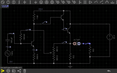
Another variation, closer to the original circuit, but with some negative feedback. Also it is intended to be built with a 2sc5200 as the output transistor which should have hFE around 100 at the operating point. The driver transistor should be a high gain device too to minimize loading on the VAS.
Attachments
I must admit I'm still attracted to the emitter follower with resistive load idea that I started out with despite its obvious disadvantages.
Nothing wrong with this at all. This type of circuit sounds great, just not practical above a few watts.
The second circuit should fair better than the first over all. Might as well throw it together and see what it does.
Nothing wrong with this at all. This type of circuit sounds great, just not practical above a few watts.
The second circuit should fair better than the first over all. Might as well throw it together and see what it does.
I ordered some more 2sc5200 last night to allow for disasters during the developmental stage! I seem to have found a reasonably cheap source of genuine Toshiba specimens ( or very good fakes! )
I will post again when I've made some progress with this. I'm still involved in the current source project and have just about finished reorganizing and inventorying all my components, many years worth and its taken me since the middle of May until now to almost complete the task! It's the summer holidays too, so I need to play my part in entertaining the kids whilst they are away from school.
Gordon.
The 2sc5200's arrived the other day, surprisingly quickly from Thailand. I'm still waiting for 50W 8 ohms load resistors. Anyone got good suggestions for the VAS transistor?
- Status
- Not open for further replies.
- Home
- Amplifiers
- Solid State
- Hot stuff- 2w Bipolar Class A Amplifier - A newbies first effort