
I basically used 28.5in H x 28.5in W x 6.5in D.The response I posted was DSP'd. That's not the natural response, just FYI. That also has room influence in it, not ground plane. So, you can't model that probably.
But if you wanted to model the natural result prediction here's dimensions:
The dimensions are 32" x 32" gross external. 1.5" internal lip under there, 3.5" around the perimeter (2x4's). Central brace is 1.5" x 3.5" x 29" length. The platform is 6.5" depth from flange of driver to the floor where the feet in the corners touch. This can slide under a cough, bed, coffee table, etc.
Very best,
Very interesting! Thanks!
I wonder if the arrangement here matters, they will be vertical and in a tower, versus horizontal here on the tower. I'm not sure if that matters, or if that is how you modeled and it's just sitting sideways. No worries either way. Very cool results in the sim. Gets me excited to work up the physical model this weekend, but I need to wait another week and finish my current project. But this one is next for sure.
Very best,
Hi there everyone,
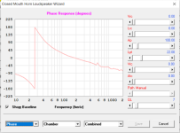
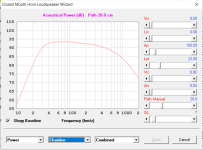
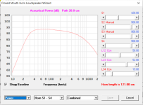
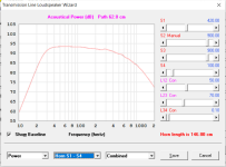
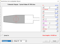
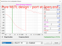
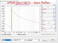
Here are two simulations done in Hornresp (firstb one pics 1/2/3/4 and then second one pics 5/6/7/8) - Same cabinet, same driver and same driver location in cabinet - the only diffrence port's type and location - ie first two graphs.
Now look at the difference in phase response...can someone explain this to me ? what are these differences in phase shift frequency meaning ? and is one preferable over the other and if so, why ?
Thanks a lot to all for your help.
Attachments


You flipped the phase description 180 degrees by describing one as a 1/4 wave design and one as a bass reflex design(even though it’s the same). Does anything happen at ~25 cm/ 344 hz because of the offset port exit distance from that closed end ? (Creates a stub?)
Very interesting! Thanks!
I wonder if the arrangement here matters, they will be vertical and in a tower, versus horizontal here on the tower. I'm not sure if that matters, or if that is how you modeled and it's just sitting sideways. No worries either way. Very cool results in the sim. Gets me excited to work up the physical model this weekend, but I need to wait another week and finish my current project. But this one is next for sure.
Very best,
You're welcome guy!
Technically, the model is a vertical arrangement with L12 & L23 = 12.625in.
Seeing that you are on all the basshead threads on avsforum.com, I @$$uMEd you might put it behind a couch.
Hi,You flipped the phase description 180 degrees by describing one as a 1/4 wave design and one as a bass reflex design(even though it’s the same). Does anything happen at ~25 cm/ 344 hz because of the offset port exit distance from that closed end ? (Creates a stub?)
First of all, thanks for your response.
Then, to be honest, I'm not sure I understood what you were implying when saying "Does anything happen at ~25 cm/ 344 hz because of the offset port exit distance from that closed end ? (Creates a stub?)"
Where do you get the 25cm measurement from ? and whatb about the 344hz thing ? ok granted in the "bass reflex" design (more about the brackets later) distance from closed end to port is just about around a full 344hz wave length, but then what ? I don't get your point because nothing special happens at or around 344hz in my design, no phase shift or whatever else, and that is with or without any stuffing too (no pics there, take my word for granted).
And then I'm all the more unsure of what you meant when you mentioned that 25cm-ish thing...?
Another thing is : it seems like the order of pics got messed up when uploading (and maybe that messed your understanding of the thing too) , which is why I took the precaution to name the pictures with numbers :
1 2 3 4 are the first design - the MLTL one with the port at the end and the phase shift around 180-190 ish.
5 6 7 8 are the second design - which was meant to be an offset port MLTL , but turned out in hornresp as a BR given the location of the phase shift, typical of a BR (fundamental frenquency just a couple hz higher).
So my question remains : could anyone help me explain the location of phase shift around 180-190hz in the MLTL design. Never saw something like that before.
And I'm curious to know if that would have any specific impact on the sound signature as I am thinking of using that design (box and port wise) for my driver.
Please know that nothing changes that phase shift location - not port size nor length, nor box size and / or length.
Driver is an SB Acoustics 10" SB26SFCL38-4
I attached Two more pics for better comprehension.
Attachments
You're welcome guy!
Technically, the model is a vertical arrangement with L12 & L23 = 12.625in.
Seeing that you are on all the basshead threads on avsforum.com, I @$$uMEd you might put it behind a couch.
Interesting thanks!
My goal is to test this manifold and see how compact I can get things while including opposition arrangement for vibration cancelation so that the tall thin depth towers don't rock or wobble and simply mass up cone area for cheap. Once I finalize the build, I'll re-do it properly with good wood and finish. The first model will be plywood or OSB just enough to function so I can measure it and stress it and see what things need to be addressed. Then, if I like it, I'll build two of them (16x drivers) with a goal of building two more (32x drivers) and likely stop there. They will fit in a common room with thier dimensions no sweat, yet conceal some compact towers of 32x drivers in a psuedo-line-array fashion. I'm curious what this output will be like and how efficient it will be for power. Ultimate goal is to have efficiency through cone area so a potato can power things to loudness.
Very best,
Very cool looking! That is quite similar as to how I'm sketching it. Just isolated slots instead of single long cavity.
The drivers are almost 6 inches depth, plus mounting material, say 3/4th inch, 2.5 to 2.75 inch cavity width, 11~12 inch depth into the cavity and height of each cavity. A few inches behind each driver, then folded baffle behind it about 12 inches again. Total baffle width is looking like 12+8+2.5+8+12=42.5 inches, height will probably be a bit more to allow the lowest driver to not sit directly on the floor, so maybe 60" total height and raise the array about 4 inches up from the footer. I'll do a slightly larger footer for stability and I like how it looks. The top will just fold over, no cap, but closed top, flush from the back. First model is just scrap. Final build will have epoxy involved to jazz up the wood and then the slots will exist inside an epoxy river down the middle.
Very best,
Man!!!Then, if I like it, I'll build two of them (16x drivers) with a goal of building two more (32x drivers) and likely stop there. They will fit in a common room with thier dimensions no sweat, yet conceal some compact towers of 32x drivers in a psuedo-line-array fashion. I'm curious what this output will be like and how efficient it will be for power.
normally people have 1 or 2 15"s or 18"s when they are bass headz
but having 16 or 32 drivers will elevate that no another level
you will be the Bazzzz Nut King!!!
masta blasta !! system!!!
i am eager looking forward the outcome of your system
as far as i read of people who added 4 or 8 subs on their room
they describe it as a visceral felling that permeate you all trough your body!
so i guess it is something that need to be experienced to be fully understood
Lucky you man !
Man!!!
normally people have 1 or 2 15"s or 18"s when they are bass headz
but having 16 or 32 drivers will elevate that no another level
you will be the Bazzzz Nut King!!!
masta blasta !! system!!!
i am eager looking forward the outcome of your system
as far as i read of people who added 4 or 8 subs on their room
they describe it as a visceral felling that permeate you all trough your body!
so i guess it is something that need to be experienced to be fully understood
Lucky you man !
I already have 16 subs as it is, just adding more and trying new things. Efficiency is the name of the game from cone area. Imagine having 100+ db SPL on all your bandwidth on like 10 watts.
Also trying to learn more about Horn Resp. Amazing software.
Very best,
Man!!!
normally people have 1 or 2 15"s or 18"s when they are bass headz
but having 16 or 32 drivers will elevate that no another level
you will be the Bazzzz Nut King!!!
masta blasta !! system!!!
i am eager looking forward the outcome of your system
as far as i read of people who added 4 or 8 subs on their room
they describe it as a visceral felling that permeate you all trough your body!
so i guess it is something that need to be experienced to be fully understood
Lucky you man !
16 or 32 drivers IS the NORM on avsforum.com.
24" drivers are becoming the NORM too.
As a matter fact, there is a 24-18's thread going on right now.
https://www.avsforum.com/threads/24x-18-go-sealed-or-stay-ported.3307422/
https://www.avsforum.com/threads/24x-18-go-sealed-or-stay-ported.3307422/
Whata!!! EFFF!!!As a matter fact, there is a 24-18's thread going on right now.
https://www.avsforum.com/threads/24x-18-go-sealed-or-stay-ported.3307422/
wow !!!
Very cool looking! That is quite similar as to how I'm sketching it. Just isolated slots instead of single long cavity.
The drivers are almost 6 inches depth, plus mounting material, say 3/4th inch, 2.5 to 2.75 inch cavity width, 11~12 inch depth into the cavity and height of each cavity. A few inches behind each driver, then folded baffle behind it about 12 inches again. Total baffle width is looking like 12+8+2.5+8+12=42.5 inches, height will probably be a bit more to allow the lowest driver to not sit directly on the floor, so maybe 60" total height and raise the array about 4 inches up from the footer. I'll do a slightly larger footer for stability and I like how it looks. The top will just fold over, no cap, but closed top, flush from the back. First model is just scrap. Final build will have epoxy involved to jazz up the wood and then the slots will exist inside an epoxy river down the middle.
Are you trying to do a square enclosure?
Are you trying to do a square enclosure?
No, rectangle W-frame baffle. About 42~44" effective width (12" wing, 8 inch front, 2.5~2.75 inch cavity width, 8 inch front, 12" wing). The height will be about 60 inches. Drivers arranged vertically in series banks on both sides of the cavity mounted behind the front baffle.
Very best,
- Home
- Loudspeakers
- Subwoofers
- Hornresp