
Are you going to have a top panel, top and bottom panels, or neither?
The top and base will be closed up, same size as the width and depth of the overall baffle.
Very best,
I updated it to allow for my intended drivers which is 8 total drivers, two banks in series and then wired in parallel to the amp.
If you want to simulate 4 stacked cabinets using a single equivalent speaker with the number of drivers increased from 2P to 2P4S, then the cross-sectional areas need to be 4 times larger, as shown below.
The normal method however would be to calculate the response for the original single cabinet with 2P drivers, and then use the Multiple Speakers tool to specify 4 speakers connected in series.
If the path lengths are set the same for the two methods then the results become identical, as shown below. The most accurate path length to use is the one given by the second method.
Hey DMB, can tell you us what is incorrect about my OD model?
You should be able to work that out for yourself - the system models are quite different.
Your design does not allow for the drivers being offset in the two outer "wings".
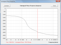
could anyone help me explain the location of phase shift around 180-190hz in the MLTL design.
It is simply due to the phase being shown wrapped to keep it within the standard -180 degree / +180 degree limits. If the phase was shown unwrapped there would be no discontinuity.
Attachment 1 shows an example of a wrapped phase response.
Attachment 2 shows the same phase response unwrapped.
Attachments

If you want to simulate 4 stacked cabinets using a single equivalent speaker with the number of drivers increased from 2P to 2P4S, then the cross-sectional areas need to be 4 times larger, as shown below.
View attachment 1353358
The normal method however would be to calculate the response for the original single cabinet with 2P drivers, and then use the Multiple Speakers tool to specify 4 speakers connected in series.
If the path lengths are set the same for the two methods then the results become identical, as shown below. The most accurate path length to use is the one given by the second method.
View attachment 1353360
Thank you so much!

🙏
I originally was just using the single cavity and then figuring that another pair was +6db and then another 2 pair was the final +6db. I was curious if the software could show it in the sim. But I think what you said about multiple speakers tool is probably more appropriate.
Very best,
You should be able to work that out for yourself - the system models are quite different.
Your design does not allow for the drivers being offset in the two outer "wings".
Thanks guy!
Can you please post a pic of the input screen to this system model?
Can you please post a pic of the input screen to this system model?
I simply used the OD3 W-frame Ripole folded baffle design shown in Post #15,079, but with area 193.55 rounded to 194.00.
If the input was taken to be voltage rather than power, then the standard frequency response curve would also become the sensitivity curve. This is simply not the case.
Updated Sensitivity Definition
Dr Bjørn Kolbrek has very kindly sent me an extract from AES standard AES2-2012 regarding sensitivity, which states:
/////////////////////////////////////////////
Sensitivity: Calculated from the frequency response and effective frequency range, as the sound pressure level produced at 1 m on the reference axis by an applied voltage of 2.83 V.
Narrow-band sensitivity: the test signal is 1/3-octave filtered noise centered at 1 kHz, or at the geometric mean of the limit frequencies of the effective frequency range if different from 1 kHz. The frequency shall be stated.
Broad-band sensitivity: the test signal is 2-octave filtered noise centered at 1 kHz, or at the geometric mean of the limit frequencies of the effective frequency range if different from 1 kHz. The frequency shall be stated.
/////////////////////////////////////////////
It is interesting that there is no longer any reference to power, which removes the ambiguity and simplifies things greatly. It also means that my statement above no longer holds true.
My apologies for any confusion caused, particularly to Crashpc.
I simply used the OD3 W-frame Ripole folded baffle design shown in Post #15,079, but with area 193.55 rounded to 194.00.
Is the Ripole option available outside of the OD3 function? Version 50.70 does not have the OD3 function.
Is the Ripole option available outside of the OD3 function?
CH3 can be used but it is not as easy to optimise the design in the Loudspeaker Wizard. Post #15,088 refers:
https://www.diyaudio.com/community/threads/hornresp.119854/page-755#post-7780509
Identical results can be produced using CH3. The downsides are that the path length is no longer automatically calculated and the area and length sliders are all independent of each other, making it more messy when trying to optimise a W-frame design in the Loudspeaker Wizard.
How do I get wings with CH3?
Also, why can't I use Ap & Lpt with CH3?
I did this model on my home laptop with version 56.70. I know I could have used OD3. However, I'm on my work laptop 99% of the time. So, I need to get CH3 right for future Ripole models.
How do I get wings with CH3?
The "wings" are just the outer air ducts of the W-frame.
The two areas are lumped together, and for your design are specified by segments 1 and 2.
why can't I use Ap & Lpt with CH3?
Because it doesn't make any sense to do so, and would defeat the purpose of the model.
Look at your own system model - there would be no connection to H3 and H4 if a port tube was specified.
I was thinking I could get the wings if:
S1 thru S3 = 58.5in x 16in each.
L12 & L23 = 6.3125in each.
S3 thru S5 = 60in x 44in each.
L34 & L45 = 0.01cm each.
Vrc = 2.5in x 58.5in x 12.625in.
Lrc = 2.5in.
Ap = 2.5in x 58.5in.
Lpt = 0.01cm.
S1 thru S3 = 58.5in x 16in each.
L12 & L23 = 6.3125in each.
S3 thru S5 = 60in x 44in each.
L34 & L45 = 0.01cm each.
Vrc = 2.5in x 58.5in x 12.625in.
Lrc = 2.5in.
Ap = 2.5in x 58.5in.
Lpt = 0.01cm.
Last edited:
I think I can get wings in CH3 by having:
Vtc = 58.5in x 16in x 12.625in.
Ltc = 58.4in x 16in.
S1 = 60in x 44in.
S2 = 60in x 44in.
L12 = 0.01cm.
S3 = 60in x 44in.
L23 = 0.01cm.
S3s = 58.5in x 2.5in.
S4 = 58.5in x 2.5in.
L34 = 6.3125in.
S5 = 58.5in x 2.5in.
S6 = 58.5in x 2.5in.
L45 = 6.3125.
Vtc = 58.5in x 16in x 12.625in.
Ltc = 58.4in x 16in.
S1 = 60in x 44in.
S2 = 60in x 44in.
L12 = 0.01cm.
S3 = 60in x 44in.
L23 = 0.01cm.
S3s = 58.5in x 2.5in.
S4 = 58.5in x 2.5in.
L34 = 6.3125in.
S5 = 58.5in x 2.5in.
S6 = 58.5in x 2.5in.
L45 = 6.3125.
Hi David,It is simply due to the phase being shown wrapped to keep it within the standard -180 degree / +180 degree limits. If the phase was shown unwrapped there would be no discontinuity.
Attachment 1 shows an example of a wrapped phase response.
Attachment 2 shows the same phase response unwrapped.
Thanks for your return.
Ok so lets say this is no great incidence.
Except that...
This is not going to be just a single driver speaker. This driver is only for the bass region. Another one takes over for mids and highs.
So there is a crossover, which I am designing in Xsim
And I'm guessing that I will need to have phases of both drivers coincide (that is, be in-phase !) to avoid sound/phase cancellation.
So to determine how to properly setup the crossover with regard to phase, should I use the phase as predicted in hornresp (with the phase shift at 180hz) or just a simple flat phase as if the driver wasn't mounted ?
My guess is to use that one as predicted in hornresp.
My guess is to use that one as predicted in hornresp.
I am no expert when it comes to crossover filters but on the face of it, your guess seems reasonable enough to me.
Someone with more knowledge of such matters may care to comment further...
- Home
- Loudspeakers
- Subwoofers
- Hornresp