As usual diyAudio drops me from notifications. Interesting work on using FreeCAD to draw a horn!
And David thanks as usual for your diligent updates.
Mark
And David thanks as usual for your diligent updates.
Mark

Post #13,279 refers.
CORRECTION:
Should be Post #13,297 not Post #13,279. Apologies for any confusion caused.
https://www.diyaudio.com/community/threads/hornresp.119854/page-665#post-7224686
Hi David, I found a bug. When using stepped segments, if you try to change the number of drivers, the stepped segment config is removed.
e.g.

Trying to change the number and arrangement of drivers results in the model being changed to this:

e.g.
Trying to change the number and arrangement of drivers results in the model being changed to this:
Hello @David McBean, as usual, many thanks for the work that you do and sharing hornresp with us. I have a feature request which might be impossible or improbable, either way, if I don't ask, I'll never know lol. Can horn resp be used to design active cardioid enclosures. I know I can use Vituixcad, its just that I prefer Hornresp and it would be cool to play around with a virtual cardioid enclosure. In particular so I can see the performance of the same cardioid box as a monopole or a Bipole depending on how you adjust delay. This same scheme would allow for bipole design I guess. I am picturing front and rear sources with width and depth at least, if not height as well... I don't know if one could implement side firing sources as well, but you are the guy to ask, so hears to asking lol.
Can horn resp be used to design active cardioid enclosures.
No, you will have to keep using VituixCAD.
Hello David,
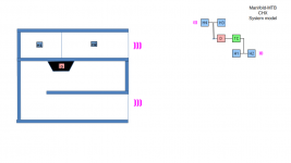
I think I asked you in the past to evaluation the possibility to implement a new Compound Horn option. Now, maybe, perhaps, new year, you could reconsider.
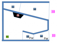
This new model would allow to evaluate different port options and layouts to improve response and particle velocity for a Parallel 6th Order band pass designs as you can see some examples from attached picture.
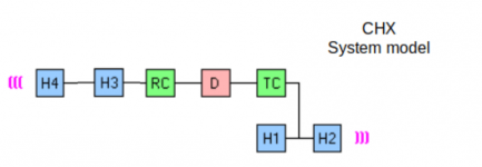
Considering the current CH1 system model, the idea is to move the H3 segment from the front to the back and connect it in series with the Rear Chamber and the the H4 segment so it became CHX.
I think I asked you in the past to evaluation the possibility to implement a new Compound Horn option. Now, maybe, perhaps, new year, you could reconsider.
This new model would allow to evaluate different port options and layouts to improve response and particle velocity for a Parallel 6th Order band pass designs as you can see some examples from attached picture.
Considering the current CH1 system model, the idea is to move the H3 segment from the front to the back and connect it in series with the Rear Chamber and the the H4 segment so it became CHX.
Attachments


I think I asked you in the past to evaluation the possibility to implement a new Compound Horn option. Now, maybe, perhaps, new year, you could reconsider.
The previous compound horn request in Post #13,174 is a bit different to the latest one.
https://www.diyaudio.com/community/threads/hornresp.119854/page-659#post-7156294
To add a new CHX loudspeaker configuration to Hornresp at this stage would require a considerable amount of work. The Input Wizard, Schematic Diagram, Loudspeaker Wizard and System Model amongst others, would all need extensive coding changes, as would the calculation modules themselves.
It is already possible to approximate the port tube using either the system shown in Attachment 1 (which includes an inner end correction), or the system shown in Attachment 2 (which does not include an inner end correction). That is going to have to be good enough…
Attachments

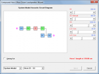
That is going to have to be good enough…
Thank you David for the feedback,
This is the current model I'm using.
Hornresp Update 5450-230128
Hi Everyone,
CHANGE
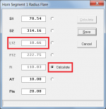
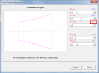
The Radius Horn Segment Wizard can now calculate L12, F12 and R given S1, S2, AT and Fta. The results obtained using this option are effectively the same as those produced by the Throat Adaptor Designer tool, as shown in Attachments 1 and 2.
BUG FIX 1
Changing the driver configuration no longer resets stepped segments to normal segments. My thanks to Brian for reporting the bug in Post #13,323.
(Changing the loudspeaker configuration in some cases continues to reset stepped segments to normal segments).
BUG FIX 2
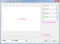
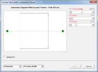
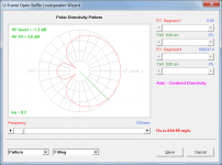
A change was made a while ago to consolidate into one global routine the multiple instances of code previously used to calculate acoustic centres. A bug was inadvertently introduced while doing this, as shown in Attachments 3 and 4. The correct results after fixing the bug are shown in Attachments 5 and 6.
Kind regards,
David
Hi Everyone,
CHANGE
The Radius Horn Segment Wizard can now calculate L12, F12 and R given S1, S2, AT and Fta. The results obtained using this option are effectively the same as those produced by the Throat Adaptor Designer tool, as shown in Attachments 1 and 2.
BUG FIX 1
Changing the driver configuration no longer resets stepped segments to normal segments. My thanks to Brian for reporting the bug in Post #13,323.
(Changing the loudspeaker configuration in some cases continues to reset stepped segments to normal segments).
BUG FIX 2
A change was made a while ago to consolidate into one global routine the multiple instances of code previously used to calculate acoustic centres. A bug was inadvertently introduced while doing this, as shown in Attachments 3 and 4. The correct results after fixing the bug are shown in Attachments 5 and 6.
Kind regards,
David
Attachments

Calculating rectangular horn cross-sections representative of our exponentially increasing horn simulations
I see a number of our colleagues' diy designs based on say 3 larger vertical and 1 horizontal (to the mouth) and several smaller rectangular sections (around corners). Is there a method at hand in HornResp I may have overlooked to transfer our smoothly increasing cross-sections to discrete steps with equivalent results? Would getting out the calculator and manually finding rectangular cross-sections for each section that gives the same volume as the exponentially increasing section be a reasonable alternative approximation, or is there other physics at play?
I see a number of our colleagues' diy designs based on say 3 larger vertical and 1 horizontal (to the mouth) and several smaller rectangular sections (around corners). Is there a method at hand in HornResp I may have overlooked to transfer our smoothly increasing cross-sections to discrete steps with equivalent results? Would getting out the calculator and manually finding rectangular cross-sections for each section that gives the same volume as the exponentially increasing section be a reasonable alternative approximation, or is there other physics at play?
I see a number of our colleagues' diy designs based on say 3 larger vertical and 1 horizontal (to the mouth) and several smaller rectangular sections (around corners). Is there a method at hand in HornResp I may have overlooked to transfer our smoothly increasing cross-sections to discrete steps with equivalent results? Would getting out the calculator and manually finding rectangular cross-sections for each section that gives the same volume as the exponentially increasing section be a reasonable alternative approximation, or is there other physics at play?
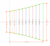
You can use any CAD software the has parametric sketch to draw the exponential profile with rectangular cross section area with the amount of point you need as much as smooth as you need, it's just about how much time you will spent on it. Unfortunately the only way to implement it is trough a discrete curve (Y,X).
You can see in the attached image and example of implementation using FreeCAD, the CAD file was also attached so you can open it and check the equations and the method I use. The example use 10 segments (discrete profile) and is fully parametric.
Hornresp can export the exponential profile for you with many points, you can import the points as a cloud points inside CAD software, but doing in this way they are not parametric and it will work just for that particular case.
Attachments
Is there a method at hand in HornResp I may have overlooked to transfer our smoothly increasing cross-sections to discrete steps with equivalent results?
Further to LORDSANSUI's comments above, tools available at the following two sites enable folded exponential horns to be approximated using parabolic segments:
https://www.diysubwoofers.org/sheets/
https://freeloudspeakerplan.rf.gd/
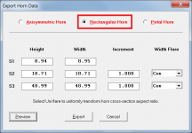
The exact dimensions of a straight-axis (unfolded) rectangular cross-section exponential horn can be found by selecting the File > Export > Horn Data menu commands from the Hornresp Schematic Diagram window and choosing the Rectangular Horn option, as shown in the attachment.
Attachments
Thanks for these replies which I will study in more detail. I perhaps didn’t find the exact words for my question I had in my head but I was thinking how to achieve the discrete rectangular prism shaped horn sections such as in Martin’s experimental enclosure I referenced in post 13205 https://www.diyaudio.com/community/threads/hornresp.119854/post-7174682 such that it adequately represents the simulated response. I can see though the potential of the freedoeakerplans and subwoofer.org alternatives.
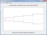
I was thinking how to achieve the discrete rectangular prism shaped horn sections such as in Martin’s experimental enclosure I referenced in post 13205
Stepped segments?
Attachments
Yes. I can create them but how should the cross sectional area of the steps be determined to achieve a similar or same response to a un-stepped folded horn if that makes sense.
how should the cross sectional area of the steps be determined to achieve a similar or same response to a un-stepped folded horn
That's for you to decide - it is very much a judgement call 🙂.
No matter what you do, it will be an approximation only.
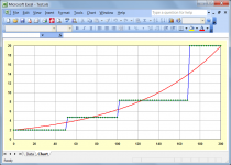
One possible approach is as shown in the attachment. The red curve plots the half-height values of a rectangular cross-section exponential horn where:
S1 = 100 cm2
S2 = 1000 cm2
L12 (Exp) = 200 cm
Fixed width of cabinet = 25 cm
Attachments
Hello David,
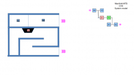
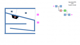
Once the new Compound Horn proposal CHX is not going to happen, and I'm also thinking about another new one CHY, but it is not going to happen too for the same reasons so I'm just posting here to populate the wish list and let some history. I like brainstorming and sharing suggestions.
While at the CHX the H3 and H4 were in series with rear chamber, at the CHY there is and offset solution, so the rear chamber/ driver feeds in between H3 and H4 as you can see in the attached images.
This architecture could allow to investigate the benefit of replacing a conventional Vented box part from the Manifold design with a Trasmission Line or MLTL solution and see if improvements could be achieved.
Attachments
David,
i got the same issue as i had before, i just click add, so my last record was copied and thats what i wanted,
then i did a simulation with another diver from the databse,
i just did the paste driver from the database
hit calculate
check the power graph, all was ok
click on the filter wizard and i got the Blue screen of death....lol i mean not on my PC but in hornresp
i got the invalid filter data, close the project, open it, click edit and press F8
and indeed i did that and it worked.
my question is, why the filter data get corrupted ? is the gremlins ?
i just tweak some with the loudspeaker wizard
and then i get this again
Last edited:
- Home
- Loudspeakers
- Subwoofers
- Hornresp