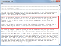
it would be great to have multiple Hornresp windows open at the same time
You are not the first person to make this observation, and I suspect that you probably won't be the last 🙂.
Unfortunately the answer remains as previously posted back in 2019:
"There are three things that will DEFINITELY never be implemented in Hornresp:
1. Additional segments.
2. The ability to view multiple chart windows simultaneously.
3. The ability to change the size of the forms."
now I find myself constantly switching between the windows.
The task can be made somewhat easier by pressing the F2 function key to quickly toggle through the windows. Also, the S key can be used to instantly check the Schematic Diagram - see the attachment for further details.
Attachments
I am planning to design a MTM with the 'M's in a transmission line.
Is there a way to put the drivers 'in line'? Like driver#1 on S2 and driver#2 on S3? That would be awesome, but I can't find a setting like that.
Or should I just take 'OD' where the virtual center of the 2 drivers is at S2?
Is there a way to put the drivers 'in line'? Like driver#1 on S2 and driver#2 on S3? That would be awesome, but I can't find a setting like that.
Or should I just take 'OD' where the virtual center of the 2 drivers is at S2?
I believe you will need to do the latter method.
Thanx, but can you help me some more? I can't find any 'latter method'.
With the OD function, segment 1 = the distance between S1 and S2 = speaker 1's diameter (L1 to L2).
Segment 2 = the distance between S2 and S3 = speaker 2's diameter (L2 to L3).
Segment 3 = the distance between S3 and S4 = your transmission line length (L3 to L4).
S2 to S3 and L2 to L3 can be combined to = speaker 2's diameter and the transmission line's length for a 2 segment model.
Segment 2 = the distance between S2 and S3 = speaker 2's diameter (L2 to L3).
Segment 3 = the distance between S3 and S4 = your transmission line length (L3 to L4).
S2 to S3 and L2 to L3 can be combined to = speaker 2's diameter and the transmission line's length for a 2 segment model.
Last edited:
Hi David,
I got the BLH with the absorber chamber simulated, it works ! 🙂
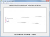
But I think there's a small bug in drawing the schematic:
The segment 4 that defines the absorber chamber is also drawn on the schematic as a 4th segment.
At first I thought that my horn was transformed in a MLTL,
but the schematic in the wizard was still correct,
also after removing the 3rd segment the bug became more clear.
Regards,
Danny
I got the BLH with the absorber chamber simulated, it works ! 🙂
But I think there's a small bug in drawing the schematic:
The segment 4 that defines the absorber chamber is also drawn on the schematic as a 4th segment.
At first I thought that my horn was transformed in a MLTL,
but the schematic in the wizard was still correct,
also after removing the 3rd segment the bug became more clear.
Regards,
Danny
Attachments
-
 BLH_Absorber_schema_2seg.gif9.2 KB · Views: 94
 -
 BLH_Absorber_2seg.gif21 KB · Views: 82
 -
 BLH_Absorber_wizard_schema1.gif14.8 KB · Views: 150
 -
 BLH_Absorber_wizard_schema.gif16 KB · Views: 141
 -
 BLH_Absorber_schema.gif7.9 KB · Views: 150
 -
 BLH_Absorber.gif19.9 KB · Views: 153
 -
Cobra2_Absorber.txt1 KB · Views: 74
Thanx, but can you help me some more? I can't find any 'latter method'.
What I meant was, the last method you mentioned in your question - you set the location of S2 at the midpoint between the two woofers, and go from there.
What I meant was, the last method you mentioned in your question - you set the location of S2 at the midpoint between the two woofers, and go from there.
OK, thanx Neil!
With the OD function, segment 1 = the distance between S1 and S2 = speaker 1's diameter (L1 to L2).
Segment 2 = the distance between S2 and S3 = speaker 2's diameter (L2 to L3).
Segment 3 = the distance between S3 and S4 = your transmission line length (L3 to L4).
S2 to S3 and L2 to L3 can be combined to = speaker 2's diameter and the transmission line's length for a 2 segment model.
Hi BP1Fanatic, thanx for reacting. I've read it 10 times, but still don't understand. Do you really mean that I should put the diameter of the drivers in the segment lengths?
I should have stated,
"Segment 1 = the distance between S1 and S2 = speaker 1's diameter OR GREATER (L1 to L2)."
That setting determines where the 2 speakers are positioned within the transmission line.
"Segment 1 = the distance between S1 and S2 = speaker 1's diameter OR GREATER (L1 to L2)."
That setting determines where the 2 speakers are positioned within the transmission line.
If you are creating a 10ft TL with 2 x 10" diameter speakers with 4" mounting depth and you want the 2 speakers at the top of the enclosure, then
Segment 1:
S1 = 25.4cm x 12.7cm (added 1 inch to allow the voicecoils to breath) = 322.58cm2.
S2 = 322.58cm2.
L12 = 25.4cm.
Segment 2:
S2 = 322.58cm2.
S3 = 322.58cm2.
L23 = 25.4cm.
Segment 3:
S3 = 322.58cm2.
S4 = 322.58cm2.
L34 = 304.8cm - 25.4cm - 25.4cm = 254cm.
If you want to move the 2 speakers to the dead center of the TL, then
L12 = 304.8/2 = 152.4cm.
L23 = 25.4cm.
L34 = 152.4cm - 25.4cm = 127cm.
Or 2 segment model:
L12 = 152.4cm.
L23 = 152.4cm.
Last edited:
If you are creating a 10ft TL with 2 x 10" diameter speakers with 4" mounting depth and you want the 2 speakers at the top of the enclosure, then
Segment 1:
S1 = 25.4cm x 12.7cm (added 1 inch to allow the voicecoils to breath) = 322.58cm2.
S2 = 322.58cm2.
L12 = 25.4cm.
Segment 2:
S2 = 322.58cm2.
S3 = 322.58cm2.
L23 = 25.4cm.
Segment 3:
S3 = 322.58cm2.
S4 = 322.58cm2.
L34 = 304.8cm - 25.4cm - 25.4cm = 254cm.
If you want to move the 2 speakers to the dead center of the TL, then
L12 = 304.8/2 = 152.4cm.
L23 = 25.4cm.
L34 = 152.4cm - 25.4cm = 127cm.
Or 2 segment model:
L12 = 152.4cm.
L23 = 152.4cm.
I think I start to understand what you mean, but with this parameters the 2 drivers are still 'on the same spot'.
What I am looking for is to play with the individual positions to optimize the response.
Gotcha!Are you referring to a gap between the 2 speakers?
In fact there is always some gap with 2 drivers, but I wanna play with it.
For a single driver around 1/4L is 'best'. For 2 drivers it will be around 3/16L + 5/16L, but how awesome would it be to play with the 2nd driver to 'correct' all the harmonic bumps?
If so, then try function OD1. I'm on my phone, so I really don't know if you can gap multiple drivers. In OD, S2 is always the middle of the drivers no matter how many drivers you model.
OD1 only puts the driver(s) at S3 instead of S2...If so, then try function OD1. I'm on my phone, so I really don't know if you can gap multiple drivers. In OD, S2 is always the middle of the drivers no matter how many drivers you model.
But I think there's a small bug in drawing the schematic
Hi Danny,
Thanks for the feedback, and for the detailed description of what you are seeing. The results I get using your 3 segment and 2 segment examples appear to be just fine - see copies attached. I have no idea why your results should be different. This is very strange indeed!
Kind regards,
David
Attachments

how awesome would it be to play with the 2nd driver to 'correct' all the harmonic bumps?
Before you ask - it's not going to happen... 🙂.
- Home
- Loudspeakers
- Subwoofers
- Hornresp