David McBean said:
It doesn't really matter - isophase wavefronts can be considered to be defined by either the red, green or black lines.
Hopefully the attached example will make things a bit clearer.
Hello,
I think we do not understand at all each other.
Never mind.
David McBean said:
As you say, just another one of life's little mysteries...
Greets!
You're welcome!
Mystery indeed! I rebooted, DL/installed V22.2, did a few sims and barely two days later awoke this morning to the low Vb message.
 DLing a couple of pdfs from a thread here are the only other 'updates' I'm aware of.
 GM
thend said:I think we do not understand at all each other.
Hi thend,
I suspect that you probably understand me okay, it's just that I am currently having some difficulty understanding you 🙂.
If anyone can clarify for me the concern that 'thend' has with the operation of the Hornresp Wavefront Simulator, then I would greatly appreciate it.
Kind regards,
David
GM said:I rebooted, DL/installed V22.2, did a few sims and barely two days later awoke this morning to the low Vb message.
Hi GM,
Just a thought - do you leave Hornresp running all the time, or do you normally close it at the end of each session? If the program is left running permanently, then perhaps you could try shutting it down after using it, to see if that makes any difference to the virtual memory problem.
Kind regards,
David
Hello David,
For what I understood Thend while using the Hornresp Wavefront Simulator tool on a tube having a given length obtained, at a given frequency, a quasi static pattern of pressure. Probably this happened at some antiresonance frequency for which the reflected wave by the mouth arrives to the throat in phase opposition with the wave emitted by the diaphragm. (it could also happen at a resonance frequency with a different pattern).
(I tried to replicate the situation but I could only obtain a slow down in the displacement of the black fronteer, without freezing).
I guess that Thend question is semantic for the most and is related to what definition we give to the word "wavefront". Even in his message Thend use the expression "propagate wavefront". (In the example of the tube at a resonance frequency there is probably a "direct wave propagation wavefront" and a "reflected wave propagation wavefront" at the same moment...).
For my own I use Mario Rossi's definition: "a wavefront is the surface linking at a given moment the points having the same given value for the considered parameter" (phase , pressure,... )
ref: Mario Rossi: "Electroacoustique".
http://www.amazon.fr/Electroacoustique-Mario-Rossi/dp/2880740614
Best regards from Paris, France
Jean-Michel Le Cléac'h
David McBean said:
Hi thend,
I suspect that you probably understand me okay, it's just that I am currently having some difficulty understanding you 🙂.
If anyone can clarify for me the concern that 'thend' has with the operation of the Hornresp Wavefront Simulator, then I would greatly appreciate it.
Kind regards,
David
Re: Re: Re: Re: Re: Re: Re: Re: Re: HORNRESP VERSION 22.10
Hello David,
When it comes to acoustic impedance prediction we know that Hornresp gives accurate results.
ref: http://www.diyaudio.com/forums/showthread.php?postid=1524736#post1524736
post #76 ,#77 ,#78 ,#79
Do we possess equivalent prooves that the power response simulation is exact (is there any measurement to compare with....)
Could you summarize the reason why a constant velocity diaphragm model is often used for FEM, BEM horn simulations?
Best regards from Paris, France
Jean-Michel Le Cléac'h
David McBean said:
Hi Jean-Michel,
The constant velocity diaphragm model is very straightforward, I wouldn't have thought that there could be too many problems with it.
Assuming the power response simulation is reasonably accurate, couldn't the rising on-axis pressure response prediction be due simply to Hornresp over-estimating "beaming" effects at higher frequencies - ie the actual beamwidth is not as narrow as that predicted by the program?
Would you still like a constant acceleration option to be added to Hornresp?
Kind regards,
David
David McBean said:
Just a thought - do you leave Hornresp running all the time, or do you normally close it at the end of each session?
Greets!
When I'm not using it it, I normally keep it minimized in the task bar. I tried closing it each time when the problem began, like I've had to do with BoxPlot 3.07 ever since I was ~forced to 'upgrade' to XP Pro, but it didn't seem to make any difference, so went back leaving it open in the task bar.
GM
Jmmlc said:For what I understood Thend while using the Hornresp Wavefront Simulator tool on a tube having a given length obtained, at a given frequency, a quasi static pattern of pressure.
Hi Jean-Michel,
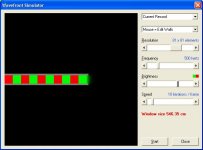
Thanks for your thoughts. As far as the Hornresp Wavefront Simulator is concerned, the isophase wavefronts shown are simply the "contour lines" connecting points of equal phase across the 2-D horn schematic diagram - much the same as the notional curved surface areas used as the basis for constructing a Le Cléac'h horn profile.
The distance between the mid-points of two adjacent red or green "lines" is equal to one wavelength at the specified frequency. The attached example shows a tube with a length of 344 cm. The tube contains exactly 5 wavelengths at the sample frequency of 500 hertz, as one would expect.
Perhaps I should point out that the Wavefront Simulator shows relative phase, not relative pressure amplitude.
Not sure what else I can say 🙂.
Kind regards,
David
Attachments
Re: Re: Re: Re: Re: Re: Re: Re: Re: Re: HORNRESP VERSION 22.10
Hi Jean-Michel,
In theory, if the predicted throat acoustical impedance is accurate, then the power response should be okay also - assuming that the diaphragm acts as a rigid plane piston and that the driver parameter values are correct.
I am not aware of any specific comparisons between predicted and measured power response. Most tests done consider the pressure response only. For bass horns though, at low frequencies where directivity is not an issue, presumably the power response could be accurately determined in an anechoic environment. Certainly a number of Hornresp users have reported a close correlation between predicted and measured results for their bass horns, even when tested under less than ideal conditions, and with folds in the horns.
Provided that a compression driver can be suitably specified using the seven electro-mechanical parameters available in Hornresp, then the power response of a midrange horn with a compression driver should also be reasonably accurate.
I have no idea why this is done. Perhaps it is simply to 'normalise' results by excluding the effect of the driver, so that only the performance of the horn is considered.
BTW, since you haven’t confirmed that the diaphragm constant acceleration option is required, it will not be included in Hornresp 🙂.
Kind regards,
David
Hi Jean-Michel,
Jmmlc said:Do we possess equivalent prooves that the power response simulation is exact (is there any measurement to compare with....)
In theory, if the predicted throat acoustical impedance is accurate, then the power response should be okay also - assuming that the diaphragm acts as a rigid plane piston and that the driver parameter values are correct.
I am not aware of any specific comparisons between predicted and measured power response. Most tests done consider the pressure response only. For bass horns though, at low frequencies where directivity is not an issue, presumably the power response could be accurately determined in an anechoic environment. Certainly a number of Hornresp users have reported a close correlation between predicted and measured results for their bass horns, even when tested under less than ideal conditions, and with folds in the horns.
Provided that a compression driver can be suitably specified using the seven electro-mechanical parameters available in Hornresp, then the power response of a midrange horn with a compression driver should also be reasonably accurate.
Jmmlc said:Could you summarize the reason why a constant velocity diaphragm model is often used for FEM, BEM horn simulations?
I have no idea why this is done. Perhaps it is simply to 'normalise' results by excluding the effect of the driver, so that only the performance of the horn is considered.
BTW, since you haven’t confirmed that the diaphragm constant acceleration option is required, it will not be included in Hornresp 🙂.
Kind regards,
David
GM said:but it didn't seem to make any difference, so went back leaving it open in the task bar.
Hi GM,
So much for that bright idea... 🙂.
Kind regards,
David
Hello David,
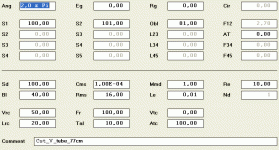
As an example of what Thend refered to, please give a look to the tube modelisation (attached screen copy)
If you use the wavefront simulator tool on 500Hz (e.g.) then follow the evolution along few minutes (2 to 5).
You'll see such events like : slow down motion of the black isophase fronteer, darkening of the whole pressure field inside the tube, apparent acceleration of the displacement...
I guess this result from some interferences between the time increment of the calculation, the used frequency, interaction between reflected and direct waves.... (for me it is not pathological...)
(BTW: to share such observations, perhaps we should study an animated gif export tool...)
Best regards from Paris, France
Jean-Michel Le Cléac'h
David McBean said:
Hi Jean-Michel,
Thanks for your thoughts. As far as the Hornresp Wavefront Simulator is concerned, the isophase wavefronts shown are simply the "contour lines" connecting points of equal phase across the 2-D horn schematic diagram - much the same as the notional curved surface areas used as the basis for constructing a Le Cléac'h horn profile.
The distance between the mid-points of two adjacent red or green "lines" is equal to one wavelength at the specified frequency. The attached example shows a tube with a length of 344 cm. The tube contains exactly 5 wavelengths at the sample frequency of 500 hertz, as one would expect.
Perhaps I should point out that the Wavefront Simulator shows relative phase, not relative pressure amplitude.
Not sure what else I can say 🙂.
Kind regards,
David
Attachments
Jmmlc said:
I guess this result from some interferences between the time increment of the calculation, the used frequency, interaction between reflected and direct waves.... (for me it is not pathological...)
I guess the same sort of thing and it's not pathological for me too.
Jmmlc said:As an example of what Thend refered to, please give a look to the tube modelisation (attached screen copy)
Hi Jean-Michel and thend,
Ah, now I understand 🙂. Many thanks Jean-Michel, for clarifying the point that thend was making.
By way of explanation, although the matrix grid defining the sound field extends some way beyond the border of the visible window, it is not infinite. When the wavefront reaches the boundary of the grid, the simulation model starts to break down.
As far as I know, there is not much that can be done about this, apart from making the grid much larger, which substantially slows the overall operation of the Wavefront Simulator.
In my case there was an additional constraint in that Visual Basic limited the size of the array that I could specify. I tried to find an acceptable compromise between size and speed.
What I hadn’t expected was that some users might want to continue running the simulator for some time after the wavefronts had reached the edge of the visible window 🙂.
Kind regards,
David
bjorno said:Can you explain why only one of the phase plots is shown unwrapped in this simulation?
Hi bjorno,
That is an easy one - there is a bug somewhere 🙂.
Thanks for reporting it, and for providing such detailed information - it really helps.
I will try to find and rectify the problem in time for the next release of Hornresp, due in the next week or so.
Kind regards,
David
David McBean said:
As far as I know, there is not much that can be done about this, apart from making the grid much larger, which substantially slows the overall operation of the Wavefront Simulator.
David
David, could you force a periodic boundary condition at that far edge, or the end of the array to zero, perhaps?
Thinking out loud
gtphill said:Could you force a periodic boundary condition at that far edge, or the end of the array to zero, perhaps?
Hi gtphill,
Thanks for your thoughts. I have tried several things like that, but nothing seems to help. It remains a "work in progress", though 🙂.
Kind regards,
David
HORNRESP VERSION 23.00
Hi Everyone,
Hornresp Version 23.00 has just been released. Product Number 2300-090703 refers.
Changes are:
* Volume details have been added to the Horn Segment Wizard. Double-click on the volume value to toggle between segment and total system volume. The feature was requested by Cordraconis.
* A Delay tool has been added to the phase response chart. The feature was suggested by Eva.
* The Range tool can now also be used with the group delay chart. The feature was suggested by Eva.
* The tapped horn phase response chart problem reported by bjorno has been fixed.
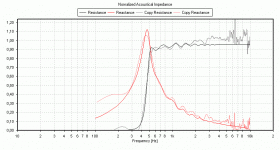
* The Le Cléac'h horn throat impedance model has been improved - in particular for horns radiating into free space.
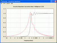
To illustrate - the attached screenprint shows the test measurement and BEM-simulated normalised throat impedance results obtained by Bjørn Kolbrek for a AH425 Le Cléac'h horn radiating into free space. The attachment in the following post shows the Hornresp-predicted normalised throat impedance for the same horn, with Ang set to 4 Pi.
Several minor bugs not related to the above changes, but discovered during Version 23 testing, have also been fixed.
Kind regards,
David
Hi Everyone,
Hornresp Version 23.00 has just been released. Product Number 2300-090703 refers.
Changes are:
* Volume details have been added to the Horn Segment Wizard. Double-click on the volume value to toggle between segment and total system volume. The feature was requested by Cordraconis.
* A Delay tool has been added to the phase response chart. The feature was suggested by Eva.
* The Range tool can now also be used with the group delay chart. The feature was suggested by Eva.
* The tapped horn phase response chart problem reported by bjorno has been fixed.
* The Le Cléac'h horn throat impedance model has been improved - in particular for horns radiating into free space.
To illustrate - the attached screenprint shows the test measurement and BEM-simulated normalised throat impedance results obtained by Bjørn Kolbrek for a AH425 Le Cléac'h horn radiating into free space. The attachment in the following post shows the Hornresp-predicted normalised throat impedance for the same horn, with Ang set to 4 Pi.
Several minor bugs not related to the above changes, but discovered during Version 23 testing, have also been fixed.
Kind regards,
David
Attachments
Re: HORNRESP VERSION 23.00
Hello David,
I just tried the new version of Hornresp.
The delay tool added to the phase response chart is very efficient and very useful (it is also very pedagocical and I am sure that now many will understand what "phase rotation" means...)
Thanks for the throat impedance improvement of the Le Cléac'h horn.
BTW: on the phase graph may be the tics marks should be put every 45°...
Best regards from Paris, France
Jean-Michel Le Cléac'h
David McBean said:
* A Delay tool has been added to the phase response chart. The feature was suggested by Eva.
* The Le Cléac'h horn throat impedance model has been improved - in particular for horns radiating into free space.
- Home
- Loudspeakers
- Subwoofers
- Hornresp