Re: Re: HORNRESP VERSION 23.00
Hi Jean-Michel,
Excellent.
You're welcome.
I will see what I can do 🙂.
Kind regards,
David
Hi Jean-Michel,
Jmmlc said:The delay tool added to the phase response chart is very efficient and very useful.
Excellent.
Jmmlc said:Thanks for the throat impedance improvement of the Le Cléac'h horn.
You're welcome.
Jmmlc said:BTW: on the phase graph may be the tics marks should be put every 45°...
I will see what I can do 🙂.
Kind regards,
David
Hi thend, Jean-Michel and gtphill,
Contrary to my earlier advice in Post #674, I have now managed to establish through further testing and analysis that the wavefront simulator problem reported by thend is in fact not triggered by the model breaking down when the wavefronts reach the boundary of the sound field grid.
After a thorough checking of the code, I have no idea what is causing the strange results - perhaps they are being generated by some kind of aliasing effect. It is interesting that the problem does not occur in all cases - it seems to depend on the test frequency chosen.
Another one of GM’s "life’s little mysteries", perhaps... 🙂.
Kind regards,
David
Re: Re: HORNRESP VERSION 23.00
Hi Jean-Michel,
The phase response chart y-axis scale increment has been reduced from 100 degrees to 45 degrees, as suggested. Product Number 2300-090704 refers.
Kind regards,
David
Jmmlc said:BTW: on the phase graph may be the tics marks should be put every 45°...
Hi Jean-Michel,
The phase response chart y-axis scale increment has been reduced from 100 degrees to 45 degrees, as suggested. Product Number 2300-090704 refers.
Kind regards,
David
This is becoming tiresome.
I am having to download a better, more comprehensive version of Hornresp every week.
When are the improvements going to stop?
David,
Thank you.
I am having to download a better, more comprehensive version of Hornresp every week.
When are the improvements going to stop?
David,
Thank you.
Re: Re: Re: HORNRESP VERSION 23.00
Hello David,
Thanks, the analysis of the phase curve is now easier withe the 45 degrees tics marks.
One thing I noticed thoughis that, the test of the phase polarity I used to insert in the phase unwrapping seems now inefficient.
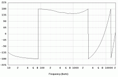
Please give a look to the attached graph. You'll see that on a very wide interval of frequency the phase is near of -180degrees or +180degrees. In such case, normally the polarity check introduce a 180 degrees shift in order to have the phase evolving around 0 degree.
Best regards from Paris, France
Jean-Michel Le Cléac'h
David McBean said:
Hi Jean-Michel,
The phase response chart y-axis scale increment has been reduced from 100 degrees to 45 degrees, as suggested. Product Number 2300-090704 refers.
Kind regards,
David
Attachments
Re: Re: Re: Re: HORNRESP VERSION 23.00
Hi Jean-Michel,
Remember, I am using:
for I = 1 : Nfreq;
PUNW(I) = PUNW(I) - Dphase * FREQ(I);
end
rather than:
for I = 1 : Nfreq;
PUNW(I) = PUNW(I) - Dphase * (FREQ(I) - FREQ(1));
end
Could this be the reason for the "inefficiency", perhaps?
Also, could you please post a screenprint of the input parameters you used to produce the phase response shown in your graph.
Did you use the default delay calculated by the program, or a different value entered with the Delay tool?
Kind regards,
David
Jmmlc said:One thing I noticed though is that, the test of the phase polarity I used to insert in the phase unwrapping seems now inefficient.
Please give a look to the attached graph.
Hi Jean-Michel,
Remember, I am using:
for I = 1 : Nfreq;
PUNW(I) = PUNW(I) - Dphase * FREQ(I);
end
rather than:
for I = 1 : Nfreq;
PUNW(I) = PUNW(I) - Dphase * (FREQ(I) - FREQ(1));
end
Could this be the reason for the "inefficiency", perhaps?
Also, could you please post a screenprint of the input parameters you used to produce the phase response shown in your graph.
Did you use the default delay calculated by the program, or a different value entered with the Delay tool?
Kind regards,
David
AndrewT said:When are the improvements going to stop?
Hi Andrew,
Just found and fixed another two bugs - Product Number is now 2300-090706 🙂.
Kind regards,
David
Re: Re: Re: Re: Re: HORNRESP VERSION 23.00
Hello David,
The last phase curve was the one obtained when running Hornresp on that example:
http://www.diyaudio.com/forums/attachment.php?s=&postid=1826078&stamp=1242139718
The "polarity check" in Matlab language is as such:
%****************************************
S1 = 0.0; S2=0.0;
for I = Imag1 : Imag2;
S1=S1+(PUNW(I)^2); S2=S2+(abs(PUNW(I))-2.3562)^2;
end
if S2>S1;
for I = 1 : Nfreq;
PUNW(I) = PHASE(I)- Dphase*FREQ(I);
PUNW(I)=PUNW(I)-2*pi*fix(0.5+(PUNW(I)/2/pi));
end
else
for I = 1 : Nfreq;
PUNW(I) = pi+( PHASE(I)- Dphase*FREQ(I));
PUNW(I)=PUNW(I)-2*pi*fix(0.5+(PUNW(I)/2/pi));
end
end
%*********************************************
All angle values in those lines of code are in radians (even the value 2.3562 which is 3/4 Pi radians and should be replaced by 270 if your own Visual Basic code uses degrees for angle values .
It only should be performed one time only (for the default "modified phase curve"), then when using the "added delay tool" it should not be done anymore.
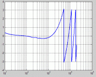
You'll find in attached file the same phase curve as obtained using my Matlab code.
Best regards from Paris, France
Jean-Michel Le Cléac'h
David McBean said:
Hi Jean-Michel,
Remember, I am using:
for I = 1 : Nfreq;
PUNW(I) = PUNW(I) - Dphase * FREQ(I);
end
rather than:
for I = 1 : Nfreq;
PUNW(I) = PUNW(I) - Dphase * (FREQ(I) - FREQ(1));
end
Could this be the reason for the "inefficiency", perhaps?
Also, could you please post a screenprint of the input parameters you used to produce the phase response shown in your graph.
Did you use the default delay calculated by the program, or a different value entered with the Delay tool?
Kind regards,
David
Attachments
Re: Re: Re: Re: Re: Re: HORNRESP VERSION 23.00
Hello David,
You surely corrected my sentence (see quotation) that should be:
"All angle values in those lines of code are in radians (even the value 2.3562 which is 3/4 Pi radians and should be replaced by 135 if your own Visual Basic code uses degrees for angle values ."
Best regards from Paris, France
Jean-Michel Le Cléac'h
Jmmlc said:
All angle values in those lines of code are in radians (even the value 2.3562 which is 3/4 Pi radians and should be replaced by 270 if your own Visual Basic code uses degrees for angle values .
Re: Re: Re: Re: Re: Re: HORNRESP VERSION 23.00
Hi Jean-Michel,
I had been using the original code you sent me:
%************************************
% set phase between -pi and +pi for graph output
%************************************
if abs(PUNW(Imag1))<pi/2.5;
PUNW=mod(PUNW+pi, 2*pi)-pi;
else
PUNW=mod(PUNW, 2*pi)-pi;
end
I will change to the new code. Thanks.
Kind regards,
David
Jmmlc said:The "polarity check" in Matlab language is as such:
Hi Jean-Michel,
I had been using the original code you sent me:
%************************************
% set phase between -pi and +pi for graph output
%************************************
if abs(PUNW(Imag1))<pi/2.5;
PUNW=mod(PUNW+pi, 2*pi)-pi;
else
PUNW=mod(PUNW, 2*pi)-pi;
end
I will change to the new code. Thanks.
Kind regards,
David
Re: Re: Re: Re: Re: Re: Re: HORNRESP VERSION 23.00
Hello David,
Yes, it is better to use the newer version of the polarity check as it analyses the phase over the useful bandwith.
Best regards from Paris, France
Jean-Michel Le Cléac'h
Hello David,
Yes, it is better to use the newer version of the polarity check as it analyses the phase over the useful bandwith.
Best regards from Paris, France
Jean-Michel Le Cléac'h
David McBean said:
Hi Jean-Michel,
I had been using the original code you sent me:
%************************************
% set phase between -pi and +pi for graph output
%************************************
if abs(PUNW(Imag1))<pi/2.5;
PUNW=mod(PUNW+pi, 2*pi)-pi;
else
PUNW=mod(PUNW, 2*pi)-pi;
end
I will change to the new code. Thanks.
Kind regards,
David
Re: Re: Re: Re: Re: Re: Re: Re: HORNRESP VERSION 23.00
Hi Jean-Michel,
Thanks. Product Number 2300-090709 containing the newer code has just been released.
Kind regards,
David
Jmmlc said:Yes, it is better to use the newer version of the polarity check as it analyses the phase over the useful bandwith.
Hi Jean-Michel,
Thanks. Product Number 2300-090709 containing the newer code has just been released.
Kind regards,
David
Hi Jean-Michel,
Excellent.
Thank you, for providing the necessary code 🙂.
Kind regards,
David
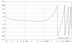
Jmmlc said:As we can see looking at the attached phase curve, the polarity check is OK in the new version of Hornresp.
Excellent.
Jmmlc said:Thank you for that.
Thank you, for providing the necessary code 🙂.
Kind regards,
David
David,
I'm a Mac user, and I'm thinking of buying an old PC to run HR. What is the oldest/slowest machine you'd think adequate? I may get something decent, but if I can find a $50 machine that'll do it, I'd be happy.
pj
I'm a Mac user, and I'm thinking of buying an old PC to run HR. What is the oldest/slowest machine you'd think adequate? I may get something decent, but if I can find a $50 machine that'll do it, I'd be happy.
pj
Hi David
In product 2300-090709 I still get almost 0 degree phase shift at 10Hz for a small sealed box that rolls off well above 10Hz, or in a plain front loaded horn also rolling off well above 10Hz.
I think phase is still wrong, at least polarity reversed.
In product 2300-090709 I still get almost 0 degree phase shift at 10Hz for a small sealed box that rolls off well above 10Hz, or in a plain front loaded horn also rolling off well above 10Hz.
I think phase is still wrong, at least polarity reversed.
If you have a recent MAC with Intel-CPU, try one of the virtual-PC techologies like parallels, vmware, etc... Simply install a windows within and you´re good to go. A bootcamp-variant should work, too and maybe you get hornresp running directly within your MAC environment via Wine, I remember some Linux-People doing it this way, so you should be ok on a MAC, too, since WINE is available...pjanda1 said:David,
I'm a Mac user, and I'm thinking of buying an old PC to run HR. What is the oldest/slowest machine you'd think adequate? I may get something decent, but if I can find a $50 machine that'll do it, I'd be happy.
pj
Give me a sign if you need help, then I´ll take a hornresp copy up to the office to the MAC and see if I can fiddle something together 🙂
pjanda1 said:What is the oldest/slowest machine you'd think adequate?
Hi pj,
If you can't get Hornresp to run on your Mac using one of Sabbelbacke's suggested methods, then any PC having Windows 95 or later as an Operating System should be okay.
Kind regards,
David
Hi Jean-Michel,
Would you care to comment on Eva's statement below?
As you know, I am no expert when it comes to "corrected" phase 🙂.
Thanks.
Kind regards,
David
Would you care to comment on Eva's statement below?
Eva said:In product 2300-090709 I still get almost 0 degree phase shift at 10Hz for a small sealed box that rolls off well above 10Hz, or in a plain front loaded horn also rolling off well above 10Hz. I think phase is still wrong, at least polarity reversed.
As you know, I am no expert when it comes to "corrected" phase 🙂.
Thanks.
Kind regards,
David
Hello David,
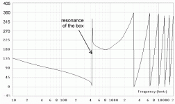
For closed box simulated by Hornresp the phase at frequency lower than the cut-off is OK (raises over +180degrees when frequency decreases, for f<10Hz) but this requires that internal resonances inside the box are masked or damped using a thick layer of damping material (example given TAL = 10cm). In the case damping is inefficient to damp the internal resonance of the box, then we may see on the response curve one or several thin deep hole(s) . In that case the mean group delay inside the useful bandwith is much affetced by the resonance and even the definition of the frequency limits of the useful bandwith are questionable. The solution is to mask the internal resonances of the box or to use a thicker damping inside the box.
The reason why someone could have some interest in the knowledge of the true polarity of the signal out of the useful bandwith is not clear to me. Even I cannot imagine this is somewhat useful except to compare to a theorical model.
The "modified" phase graph in Hornresp is a tool the goal of which is to facilitate to everyone the optimisation of a given horn/enclosure. I think that as it is, this tool reaches its goal.
But we can imagine an elegant solution to the problem raised by Eva. When the polarity check module detects a phase inversion inside the useful bandwith, then 180 degrees should be added to the values of the marks on the vertical axis. You'll find an example in the attached graph. Another simpler solution should be that the polarity could be written near the applied delay at the top of the modified phase graph. (Eventually a phase inversion button should be eventually added to the delay cursor control in the "tools")
Best regards from Paris, France
Jean-Michel Le Cléac'h
David McBean said:Hi Jean-Michel,
Would you care to comment on Eva's statement below?
As you know, I am no expert when it comes to "corrected" phase 🙂.
Thanks.
Kind regards,
David
Attachments
- Home
- Loudspeakers
- Subwoofers
- Hornresp


