Hey!
I've shuffled around HornResp before, but ended up getting lots of help with a design.
Beside reading 700+ pages of this thread, is there somewhere I can go for a guide to find out:
- are S parameters in cm?
- how to design QW, TQ, MLTL,
etc?
TIA!
I've shuffled around HornResp before, but ended up getting lots of help with a design.
Beside reading 700+ pages of this thread, is there somewhere I can go for a guide to find out:
- are S parameters in cm?
- how to design QW, TQ, MLTL,
etc?
TIA!
is there somewhere I can go for a guide
The Hornresp Help file would be a good place to start.

Hi There,
I am trying to understand better the maths/geometry behind hyperbolic horns and how hornresp works.
In the Letters to the Editor section on page 11 of the Leache horn paper it gives the formula for the cross-sectional area of a hyperbolic horn. https://pearl-hifi.com/06_Lit_Archi...each_Marshall/SPICE_Modeling_Salmon_Horns.pdf How does hornresp handle the X0 variable (the reference axial)?
Many Thanks
formula for the cross-sectional area of a hyperbolic horn
Given:
S1
S2
L12
T
Then:
A = 1 + T
B = -Sqrt(4 * S2 / S1)
C = 1 - T
m = Ln((-B + Sqrt(B ^ 2 - 4 * A * C)) / (2 * A)) / L12
Sx = S1 / 4 * ((1 + T) * Exp(m * Lx) + (1 - T) * Exp(-m * Lx)) ^ 2
Where Sx = cross-sectional area at distance Lx from hyperbolic-exponential horn throat
Does X0 need to be handled in a special way? It's simply c/(2*pi*fc) where c is the speed of sound and fc is the cutoff frequency. It is identical to 1/m, where m is calculated as David describes above.How does hornresp handle the X0 variable (the reference axial)?
FWIW, almost 20 years ago I built a sub like this, 3 ports running lengthwise, between the subs (to get enough length / port area in a smallish box) for a friend.ok, great. 🙂
Thank you!
Dayton "car" sub version of one of their good HT subs... and it sounded GREAT. Built the whole thing out of 1" MDF, 70lbs of that plus 40lbs of sub, the whole thing SHOOK his car. only a couple 12s, but hit well over 130db at the dash, at almost any frequency we wanted. AND it had transient punch.
Hi all, I'm building a floor stander and I'm trying to predict the port resonance frequency and expected interference with the driver response. I have two questions when using the off-set port bass reflex design:
1) When specifying the distance between the driver and the port (i.e. "Con" second one down), is this this the distance between the driver and the port opening inside the cabinet, or the port opening outside the cabinet? I guess when the port is facing the baffle or the back side, it would be the same, but I have a down-firing port in my speaker.
2) Is one supposed to technically subtract the volume consumed by the port? In other words, the area specified between S3 - S3 / Con should be reduced by the volume consumed by the port? or does the software automatically do that based on the port dimensions specified by "Ap" and "Lpt"
3) Still struggling with how to specify "Path". Is that the shortest distance between the center of the driver and the center of the port if you ran one of those flexible tape measures around the outside of the cabinet?
Clemenules provided some useful examples, including a downfiring one, later confirmed by David a while back see post https://www.diyaudio.com/community/threads/hornresp.119854/post-7266491. Searching on "path" in the help file in the help menu, several entries come up. Depending on the circumstances, path can be automatically calculated or manually entered.distance between the driver and the port
1) When specifying the distance between the driver and the port, is this the distance between the driver and the port opening inside the cabinet, or the port opening outside the cabinet?
It is the distance between the driver and the port opening inside the cabinet.
2) Is one supposed to technically subtract the volume consumed by the port?
No. The cabinet volume is simply the sum of the segment volumes. The port tube volume is treated separately.
3) Still struggling with how to specify "Path".
The driver radiator and the port opening outside the cabinet are considered to be acoustic point sources. The path length is the straight line distance between the two sources, assuming that the cabinet does not exist.
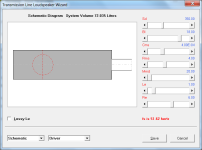
(The system model in the loudspeaker wizard shows how the design is interpreted by Hornresp).
Thanks, David. Considering that the port is inside the cabinet (as opposed to hanging outside the cabinet), doesn't it otherwise take away from the volume that exists? Or does the software automatically assume the port extends inside the cabinet?No. The cabinet volume is simply the sum of the segment volumes. The port tube volume is treated separately.
The simulation model assumes that the port tube "hangs outside the cabinet".
The area representing the cabinet volume is shown in grey in the attachment.
The cabinet volume is the effective enclosed air volume behind the driver diaphragm, including any space occupied by acoustical lining or absorbent filling material but excluding port tube, driver magnet and chassis assemblies.
Attachments
Considering that the port is inside the cabinet (as opposed to hanging outside the cabinet), doesn't it otherwise take away from the volume that exists?
If you want to think of it that way, then yes, you need to take the volume of the actual physical cabinet and subtract the port tube volume. (This is in effect what I have said in my post above).
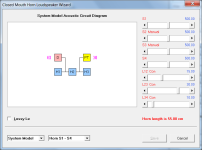
I tend to think of the chamber and port tube as separate but interconnected lumped elements in an acoustic circuit, each component having its own independent volume. I don't worry too much about how they are actually arranged in practice.
In the attachment, the areas representing the cabinet volume are shown in blue, and the area representing the port tube volume is shown in yellow.
Attachments
Last edited:
The area representing the cabinet volume is shown in grey in the attachment.
Got it. I'm using the offset port model, so my image was showing up as below. I'll adjust the volume for the port. Thanks for clarifying.
Thanks for clarifying
Sorry for the initial confusing information, we were looking at the issue from different viewpoints.
Because Hornresp does not know how the loudspeaker is to be physically constructed it cannot allow for the port tube and automatically adjust the chamber volume accordingly. In practice the port tube could be inside the cabinet, outside the cabinet or perhaps even part inside / part outside. This is why it is necessary for the user to specify the chamber net volume.
but it's an iterative tool (you need to adjust a slider to achieve a target Fb), rather than a tool that will just give you the required Lpt for a given Fb in one step.
In the next update there will be an option to accurately calculate the required Lpt for a given Fb, assuming that Vrc, Lrc and Ap are known.
Given:
S1
S2
L12
T
Then:
A = 1 + T
B = -Sqrt(4 * S2 / S1)
C = 1 - T
m = Ln((-B + Sqrt(B ^ 2 - 4 * A * C)) / (2 * A)) / L12
Sx = S1 / 4 * ((1 + T) * Exp(m * Lx) + (1 - T) * Exp(-m * Lx)) ^ 2
Where Sx = cross-sectional area at distance Lx from hyperbolic-exponential horn throat
Thank you! This is incredibly helpful!
@Kolbrek, thanks for pointing that out, I didn't see that formula on the next page; feel a bit silly now....
Remember to account for the volume occupied by the walls of the port tube. It might not be significant, but then again it might.Thanks, David. Considering that the port is inside the cabinet (as opposed to hanging outside the cabinet), doesn't it otherwise take away from the volume that exists? Or does the software automatically assume the port extends inside the cabinet?
Hornresp Update 5520-231031
Hi Everyone,
CHANGE 1
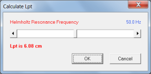
The operation of the Helmholtz resonance frequency calculation tool has been reversed so that Lpt is now calculated given the Helmholtz resonance frequency, rather than the Helmholtz resonance frequency being calculated given Lpt. Attachment 1 refers.
If the Helmholtz Resonance Frequency label is double-clicked the Helmholtz resonance frequency can still be calculated given Lpt.
(Any slight changes in frequency or Lpt values when switching from one calculation mode to the other are due to frequency input values being rounded to one decimal place and Lpt input values being rounded to two decimal places).
For a given Helmholtz resonance frequency, because of the way that the Lpt value is being calculated, the Hornresp result should theoretically be more accurate than that produced by most other box programs, particularly when the port tube is relatively long.
CHANGE 2
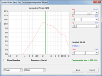
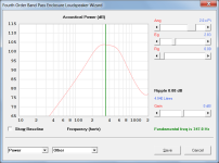
The BP4 wizard auto design feature has been enhanced. The calculated results are now closer to the optimised ideal. Attachment 2 shows the old result for a given driver. Attachment 3 shows the new result using the same driver, gain and ripple settings.
CHANGE 3
The closed box loudspeaker design tool now has two alignment options:
Default Alignment
Leach Alignment
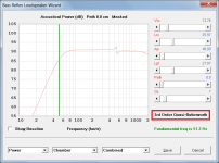
The bass reflex loudspeaker design tool now has four alignment options:
Default Alignment
4th Order Butterworth
3rd Order Quasi-Butterworth
4th Order Chebyshev
Attachment 4 refers.
See the 'Design Wizard - Closed Box' and 'Design Wizard - Bass Reflex' sections in the Hornresp Help file for further details.
Kind regards,
David
Hi Everyone,
CHANGE 1
The operation of the Helmholtz resonance frequency calculation tool has been reversed so that Lpt is now calculated given the Helmholtz resonance frequency, rather than the Helmholtz resonance frequency being calculated given Lpt. Attachment 1 refers.
If the Helmholtz Resonance Frequency label is double-clicked the Helmholtz resonance frequency can still be calculated given Lpt.
(Any slight changes in frequency or Lpt values when switching from one calculation mode to the other are due to frequency input values being rounded to one decimal place and Lpt input values being rounded to two decimal places).
For a given Helmholtz resonance frequency, because of the way that the Lpt value is being calculated, the Hornresp result should theoretically be more accurate than that produced by most other box programs, particularly when the port tube is relatively long.
CHANGE 2
The BP4 wizard auto design feature has been enhanced. The calculated results are now closer to the optimised ideal. Attachment 2 shows the old result for a given driver. Attachment 3 shows the new result using the same driver, gain and ripple settings.
CHANGE 3
The closed box loudspeaker design tool now has two alignment options:
Default Alignment
Leach Alignment
The bass reflex loudspeaker design tool now has four alignment options:
Default Alignment
4th Order Butterworth
3rd Order Quasi-Butterworth
4th Order Chebyshev
Attachment 4 refers.
See the 'Design Wizard - Closed Box' and 'Design Wizard - Bass Reflex' sections in the Hornresp Help file for further details.
Kind regards,
David
Attachments
Awesome! I missed this post and was directed to it by @grindstone. It fixed it for me (I was trying to use micross.ttf, which was clearly misguided). The only caveat for me was that I had to fix the file ownership (and permissions to be on the safe side) since I was using sudo to copy the fonts here, there and everywhere in my previous vain efforts.Finally i found a solution, thank you for everyone that helped 🙂
solution was easy :
get the ms sans serif font file from a windows device and then past it in my .wine/drive_c/windows/fonts folder on my linux device. then hornresp launched properly 🙂
the font file is in attachement (sserife.fon).
Hi David would it be possible to add a similar search option as 'File Open' to the 'Paste Driver from Database...' selection menu. It would be extremely helpful to make browsing through a list of 500+ drivers more pleasant.
- Home
- Loudspeakers
- Subwoofers
- Hornresp