Hello David, I actually was serious
Hi Ivo,
Either way, it's still not going to happen 🙂.
Kind regards,
David
Hi David, absolutely entirely up to you, but I would be interested to know why. Technical/programming reasons?
A kind of option would also improve precise simulation of keystone sub design once its mounth in some way is similar to karlson
I think the very longest length will give the most accurate representation of displacement and large signal impedance below cutoff
Hi Fred,
Just confirming that your suggestion to use a port tube length value of 99999.99 rather than 0.01 when "closing" a port, is definitely the way to go. Further comparative testing has shown that it produces the more accurate result under all conditions.
Thanks for providing the link to the Martin Poppe paper. Out of interest I downloaded a copy and had a look through it. Unfortunately the model discussed has the driver oriented perpendicular to the K-coupler opening, which as far as I am aware is not the case with a typical Karlson enclosure. Also, there is no direct comparison of the input impedance predicted by the model and actual measured performance. The predicted performance of a comparably-dimensioned exponential horn is given instead, which is not particularly helpful when trying to determine the accuracy of the model.
Kind regards,
David
Technical/programming reasons?
Hi Ivo,
Yes, both in fact 🙂.
Technical - No suitable theoretical model.
Programming - Difficulty in specifying the K-coupler dimensions, and how the slot element itself is positioned / oriented relative to the rest of the loudspeaker system. More input parameters would need to be added to Hornresp to address this issue, which in turn would mean that extra fields would need to be added to the data file record. This is not something that I want to do - things are complicated enough already 🙂.
If you can come up with a robust and accurate model, and work out a way to specify the K-coupler slot in a loudspeaker system without requiring any additional input parameters in Hornresp, then I would certainly be prepared to reconsider my position...
Kind regards,
David
Hi David
Poppe was using a 6x9 car speaker to excite the test coupler - also a (homemade ?) traveling wave tube. The paper could have been better and more complete in several areas. Testing was done at MIT as Poppe's thesis.
I'm hoping for Matthew Morgan J to explain the fudge factors in his Karlflex w. stub model as to what may be adjusted with some confidence and how to translate other proportions to that model.
Best,
Fred
Last edited:
Hornresp Update 5020-190623
Hi Everyone,
CHANGE
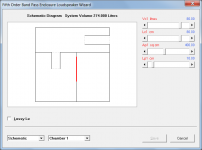
Another two band pass loudspeaker configurations have been added, as shown in Attachment 1.
The first new configuration is defined in Hornresp as a fifth order band pass system, with the designation BP5, and has the topology shown in Attachments 2 and 3. It is in effect a fourth order system, but with the addition of a second ported chamber connected in series with the first.
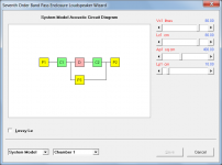
The second new configuration is defined in Hornresp as a seventh order band pass loudspeaker, with the designation BP7, and has the topology shown in Attachments 4 and 5. It is in effect a sixth order parallel system, but with the addition of a third port between the two chambers.
Disclaimer - I am not sure that strictly speaking the two new configurations should be classified as fifth order and seventh order, but it is certainly convenient to designate them as such in Hornresp, and to give them the three-character labels BP5 and BP7.
I would be interested if anyone can suggest more accurate / meaningful titles, on the understanding that the label names would still need to be limited to three characters 🙂.
BUG FIX
Results were not being correctly calculated for a sixth order parallel bandpass enclosure with offset driver. This problem has now been fixed.
Kind regards,
David
Hi Everyone,
CHANGE
Another two band pass loudspeaker configurations have been added, as shown in Attachment 1.
The first new configuration is defined in Hornresp as a fifth order band pass system, with the designation BP5, and has the topology shown in Attachments 2 and 3. It is in effect a fourth order system, but with the addition of a second ported chamber connected in series with the first.
The second new configuration is defined in Hornresp as a seventh order band pass loudspeaker, with the designation BP7, and has the topology shown in Attachments 4 and 5. It is in effect a sixth order parallel system, but with the addition of a third port between the two chambers.
Disclaimer - I am not sure that strictly speaking the two new configurations should be classified as fifth order and seventh order, but it is certainly convenient to designate them as such in Hornresp, and to give them the three-character labels BP5 and BP7.
I would be interested if anyone can suggest more accurate / meaningful titles, on the understanding that the label names would still need to be limited to three characters 🙂.
BUG FIX
Results were not being correctly calculated for a sixth order parallel bandpass enclosure with offset driver. This problem has now been fixed.
Kind regards,
David
Attachments


Hi David,
That is really awesome to tweak port size, it's surprising conter intuitive to see that first segment are lower velocity. Thanks a lot, again !
While you there, there's the (non re-entrant) parrallel 7th, adding a bp to a parrallel 6th order, or venting the 5th order back chamber ^^. Can be actually too simed with PR in Nd/OD actually.
(comment : i use to like smooth response for some reasons, so for some, those are not impressive sims...)
Attachments

While you there, there's the (non re-entrant) parrallel 7th, adding a bp to a parrallel 6th order, or venting the 5th order back chamber ^^. Can be actually too simed with PR in Nd/OD actually.
Hi Damien,
I think that we might have just about run out of three-character labels, to be able to add your example to the ever-growing list of band pass enclosure options in Hornresp 🙂.
Just remember though, when simulating using Nd records, that end corrections will not be included on the internal ends of port tubes. This will change the tuning a little.
Kind regards,
David
Last edited:
I think that we might have just about run out of three-character labels
What about BP9, perhaps?
After all, it could be considered to be a modified BP8 with the chamber 2 port tube venting externally, rather than into either chamber 1 (BP8S) or chamber 3 (BP8P) 🙂.
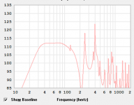
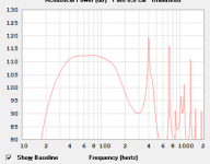
papasteack - those are impressive bandwidths - whats the input voltage and driver for the 109 liter cabinet?
for a BP7 - I didn't do so well - but it would take a 100v peak and not exceed rated 8mm
https://i.imgur.com/KErTSpr.png
for a BP7 - I didn't do so well - but it would take a 100v peak and not exceed rated 8mm
https://i.imgur.com/KErTSpr.png
Last edited:
David and other who may chime in,
I want to clear a few things for myself. I've been reading this thread but can't still grasp a few concepts.
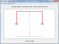
So i want to model an H-Frame in Hornresp. I get it, that in order to do so one simply models a compunded horn with the length of the sides as per required. This part is clear.
How do i get the path value?
Here is how i see the path:

The path starts from the center of the driver, goes around the frame and towards the
center of the rear of the driver. This gives 150cm in this example.
Here in this thread i've seen example of path being equal to sum of L1 and L4, equal to just L1 or L4, then there is this formula (Path length difference = W / 2 + ((W / 2) ^ 2 + 1) ^ 0.5 - 1).
Would really appreciate if somebody can dumb this down for me 🙂
Same for a nude driver with no baffle - what should be used as a path? Twice the radius? The forumaly above with W=2xRadius? Please, explain. Hornresp seems to be the easiest tool to simulate OB type speakers for me, just need a few clarifications 🙂
I want to clear a few things for myself. I've been reading this thread but can't still grasp a few concepts.
So i want to model an H-Frame in Hornresp. I get it, that in order to do so one simply models a compunded horn with the length of the sides as per required. This part is clear.
How do i get the path value?
Here is how i see the path:
The path starts from the center of the driver, goes around the frame and towards the
center of the rear of the driver. This gives 150cm in this example.
Here in this thread i've seen example of path being equal to sum of L1 and L4, equal to just L1 or L4, then there is this formula (Path length difference = W / 2 + ((W / 2) ^ 2 + 1) ^ 0.5 - 1).
Would really appreciate if somebody can dumb this down for me 🙂
Same for a nude driver with no baffle - what should be used as a path? Twice the radius? The forumaly above with W=2xRadius? Please, explain. Hornresp seems to be the easiest tool to simulate OB type speakers for me, just need a few clarifications 🙂
Hi StabMe,
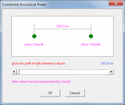
For the purposes of calculating combined power response, the path value is the length of the shortest acoustic path between the two outputs (assumed to be point sources).
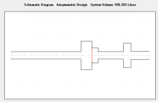
The red line in Attachment 1 indicates the theoretical path for your example design, with the length being 25+50+25 = 100 cm. The point sources are located at the two "mouths" of the system, as indicated in Attachment 2.
Assuming a point source on each side, and at the centre of the diaphragm, then yes, the path length will be the distance from the front point source around the diaphragm to the rear point source.
Things are never this straight-forward in practice though, and the point source assumption may not necessarily be valid for all system designs, or at all frequencies.
Kind regards,
David
So i want to model an H-Frame in Hornresp. How do i get the path value?
For the purposes of calculating combined power response, the path value is the length of the shortest acoustic path between the two outputs (assumed to be point sources).
The red line in Attachment 1 indicates the theoretical path for your example design, with the length being 25+50+25 = 100 cm. The point sources are located at the two "mouths" of the system, as indicated in Attachment 2.
Same for a nude driver with no baffle - what should be used as a path? Twice the radius?
Assuming a point source on each side, and at the centre of the diaphragm, then yes, the path length will be the distance from the front point source around the diaphragm to the rear point source.
Things are never this straight-forward in practice though, and the point source assumption may not necessarily be valid for all system designs, or at all frequencies.
Kind regards,
David
Attachments
- Home
- Loudspeakers
- Subwoofers
- Hornresp