Does your phase plug separate the chamber in half so each driver sees only the exit and not the other driver?[QUOTE ]
You win the golden cookie award!
Nice reference Bill. That was much of what I was thinking.
BMS also has a dual compression driver setup that is interesting.
BMS also has a dual compression driver setup that is interesting.
Conjecture
For any HF horn, of either round or rectangular section, use an O.S. profile (hyperbola of increasing radius of curvature). Then finish it off with a mouth, using the Le Cleac'h method to implement a gradual decline in the radius of curvature. Or use a fairness curve to implement the entire profile as presented in an earlier post. N.B.: The only reason for flat horn walls, is cost.
WHG
>snip<
The question is in a nutshell can a multiple driver horn be something other than a conic?
>snip<
For any HF horn, of either round or rectangular section, use an O.S. profile (hyperbola of increasing radius of curvature). Then finish it off with a mouth, using the Le Cleac'h method to implement a gradual decline in the radius of curvature. Or use a fairness curve to implement the entire profile as presented in an earlier post. N.B.: The only reason for flat horn walls, is cost.
WHG
Line Source Array
You can array two vertically in the horn throat to serve as a extended line source. If they deliver on their promise, lobbing in the pass-band should be negligible. WHG
Nice reference Bill. That was much of what I was thinking.
BMS also has a dual compression driver setup that is interesting.
You can array two vertically in the horn throat to serve as a extended line source. If they deliver on their promise, lobbing in the pass-band should be negligible. WHG
For high SPL a compression driver is great.
For hifidelity I do not find a compression driver as clean sounding as a planar. Hence the reasoning behind making a planar almost as efficient.
For hifidelity I do not find a compression driver as clean sounding as a planar. Hence the reasoning behind making a planar almost as efficient.
I talked this over with a friend of mine. Dan Finley. He pointed out quite accurately that if the horn has a common throat entry for a driver manifold that this is already possible in HOrnresp.
Insert Forehead slap....
Yep.
Still wondering on the application of taking a multiple entry horn into the realm of curved horns versus conics.
Because I could take this quite a bit farther than what I originally thought about.
Imagine a true hifidelity multiple entrance LeCleach Horn.
Square mouth could almost launch a circular wavefront. So as close to point source as is possible with control of radiation angle.
Gots me a thinking for sure.
For high SPL a compression driver is great.
For hifidelity I do not find a compression driver as clean sounding as a planar. Hence the reasoning behind making a planar almost as efficient.
When you apply LF horn design principals that emphasize driver loading in stead of pattern control and HOM mitigation, then HF radiation from such designs will certainly exhibit the characteristics you describe. In most cases this is not the fault of the driver, which in the "Hi Fi" setting, is being operated at levels less than 10% of its capacity. WHG
Still wondering on the application of taking a multiple entry horn into the realm of curved horns versus conics.
Hi Mark,
If you mean 'multiple entry horn' as defined in Hornresp, then up to four conical, exponential or parabolic segments can be specified, with a minimum of two being required.
If you mean 'multiple entry horn' as in multiple drivers, then it depends on how the drivers are arranged. If the normal Nd arrangement is used with a single segment horn then any of the nine available flare profiles can be specified. If the offset driver OD arrangement is used then at least two segments must be specified, with flares types limited to conical, exponential or parabolic.
Kind regards,
David
I will see how closely I can approximate what I am hoping for with the system you have in place.
Thanks for looking at my idea David.
Hi !
Sorry for the little off-topic, i'm not sure, but i suspect i should get a response here since this thread concentrate interest of people with lot of physical knowledge of how sound work... So, even if it can appear stupid, i ask !
Would be really curious to know if some kind of modulation/demodulation of multiple signal on different speaker should work with sufficient front bandpass box... for example 4khz on the first speaker, and 4,1khz on the second, a big mixing bandpass front chamber...what happen ? do we get 100hz, and at what level ? Sufficient bandpass box can allow around 40db filtering few octave higher. I know it's a oversymplifying idea compared to how sound work, and it seems interesting to explore.
I would have simulate it with wavefront tool if it where possible to specify different frequencies for each sources. So, does it make any sense ?
Last edited:
Hi !
Sorry for the little off-topic, i'm not sure, but i suspect i should get a response here since this thread concentrate interest of people with lot of physical knowledge of how sound work... So, even if it can appear stupid, i ask !
Would be really curious to know if some kind of modulation/demodulation of multiple signal on different speaker should work with sufficient front bandpass box... for example 4khz on the first speaker, and 4,1khz on the second, a big mixing bandpass front chamber...what happen ? do we get 100hz, and at what level ? Sufficient bandpass box can allow around 40db filtering few octave higher. I know it's a oversymplifying idea compared to how sound work, and it seems interesting to explore.
I would have simulate it with wavefront tool if it where possible to specify different frequencies for each sources. So, does it make any sense ?
You are hoping for a reproduction of a beat tone?
This is done with ultrasonic arrays. Also done in radio applications.
And probably can be done in the audio band. But what are you trying to do?
Within the audio band I'm guessing that there will not be anywhere near enough of a cancellation of the common frequency to allow the desired upper or lower frequency to be useful.
I'm hopping to do as ultrasonic array exactly, using a important enough front bandpass chamber arrangement to cancel carrier wave, using so not so big excursion speakers to produce midrange carrier wave to finally get subrange tone...Don't know if it would be interesting. It looks to me as a kind of acoustic class D sub. Probably not worth a try, but idea is fun.
EDIT : In fact, thinking about it again, it should already be simulated using very insane high slope filter with multi-entry wizard ! Probably easier to tweak with akabak....I'll play and see.
EDIT : In fact, thinking about it again, it should already be simulated using very insane high slope filter with multi-entry wizard ! Probably easier to tweak with akabak....I'll play and see.
Last edited:
The ultrasonic arrays operate at levels of 130-150dB and use the resulting air nonlinearity to generate beats, which aren't all that loud actually. You will probably need similar levels to generate the beats if you rely on air nonlinearity. And filtering a 150dB 4kHz tone down to inaudibility will be quite challenging. (Think notch filters). 4kHz is in the most sensitive frequency range of the ear, and tonal noise is more annoying than random noise.
Maybe it can be done, but the cost would probably be way higher than that of a decent subwoofer driver... 🙂
Not trying to stop you or anything, just pointing out a few of the obstacles you have to get around 🙂
Maybe it can be done, but the cost would probably be way higher than that of a decent subwoofer driver... 🙂
Not trying to stop you or anything, just pointing out a few of the obstacles you have to get around 🙂
Thanks Kolbrek ! I don't really want to try, it's more about curiosity, 4khz is a stupid example, but easier range to sim in hornresp/akabak. 21khz would be a better idea to be able to use already available speaker, and at the same time beeing not so much earable.
Still at 4khz doesn't work at all in hornresp (simming two 144db tone, i see nothing in low range in the window sim starting at 105db).
David, i suspect in hornresp that with two tone of 100hz interval (using eq filters in ME tool), "intermodulation" (don't know it it the good term) of 100hz resultant is not simed. Am i right ? I'm afraid it would need finite element sim (whenever i don't know what i'm talking about ^^)...
Last edited:
David, i suspect in hornresp that with two tone of 100hz interval (using eq filters in ME tool), "intermodulation" (don't know it it the good term) of 100hz resultant is not simed. Am i right ? I'm afraid it would need finite element sim (whenever i don't know what i'm talking about ^^)...
Hi papasteack,
Not sure that I understand.
How can the ME tool equaliser filters be used to generate different frequencies at each of the two drivers in a 2-way multiple entry system?
As far as I can see, the two signals being combined will each still have the same frequency - it's only the relative levels that change due to equalisation.
Kind regards,
David
Hi papasteack,
No matter how you manipulate the controls in Hornresp, for instance by setting two peaks in the response by using the EQ, Hornresp would only simulate one frequency at the time. Also, since the system is assumed to be linear, you would not see any distortion product. You need a simulation package that takes air nonlinearity into account, and I think that also uses transient simulation, and not steady state. Some FEM packages can do that. But I'm not aware of any free or cheap packages that do nonlinear acoustics.
No matter how you manipulate the controls in Hornresp, for instance by setting two peaks in the response by using the EQ, Hornresp would only simulate one frequency at the time. Also, since the system is assumed to be linear, you would not see any distortion product. You need a simulation package that takes air nonlinearity into account, and I think that also uses transient simulation, and not steady state. Some FEM packages can do that. But I'm not aware of any free or cheap packages that do nonlinear acoustics.
Hyperbolic extension
Hi David
Got a bit confused about the F12 flare/cut-off frequency when trying to extend an existing hyperbolic horn to a much smaller throat. The application is taking an existing hyperbolic ( T = 0.6 ) horn, driven by a Fostex FE208Ez ( throat 90cm^2 ) to a much longer horn, with same final section, to be driven by a modded K-55V Klipsch driver. I wanted to know how much more length is required for the Klipsch compression driver.
So, I start with a 90 to 2600cm^2 hyperbolic, T 0.6, length 164cm. This reports 63.41Hz as the flare cutoff frequency.
The Klipsch has a tiny 2.05cm throat, so that's 3.3cm^2 .
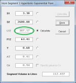
If I put in this throat value, keep the same mouth, and extend the length until I get the same 63.41 cut-off frequency , I get 307.2cm length.
If I then export the horn data and check the expansion to the original throat position , ie. at or near 307.2-164cm ( = 143.2 ) I get a value much smaller than 90cm^2 - about 60cm^2 in fact.
I have not understood something about the cut-off calculation and hyperbolic horns, I suspect.
Hi David
Got a bit confused about the F12 flare/cut-off frequency when trying to extend an existing hyperbolic horn to a much smaller throat. The application is taking an existing hyperbolic ( T = 0.6 ) horn, driven by a Fostex FE208Ez ( throat 90cm^2 ) to a much longer horn, with same final section, to be driven by a modded K-55V Klipsch driver. I wanted to know how much more length is required for the Klipsch compression driver.
So, I start with a 90 to 2600cm^2 hyperbolic, T 0.6, length 164cm. This reports 63.41Hz as the flare cutoff frequency.
The Klipsch has a tiny 2.05cm throat, so that's 3.3cm^2 .
If I put in this throat value, keep the same mouth, and extend the length until I get the same 63.41 cut-off frequency , I get 307.2cm length.
If I then export the horn data and check the expansion to the original throat position , ie. at or near 307.2-164cm ( = 143.2 ) I get a value much smaller than 90cm^2 - about 60cm^2 in fact.
I have not understood something about the cut-off calculation and hyperbolic horns, I suspect.
Hi IslandPink,
Note that the required new length value can be determined very quickly using the Horn Segment Wizard - see attachment.
If S2, F12 and T are held constant, then:
For T < 1 (hyperbolic cosine horn) the new cross-sectional area at the original throat position will be less that the original S1 value.
For T > 1 (hyperbolic sine horn) the new cross-sectional area at the original throat position will be greater that the original S1 value.
For T = 1 (exponential horn) the new cross-sectional area at the original throat position will be the same as the original S1 value.
It's just the way that the expansion formula for a hyperbolic-exponential horn works 🙂.
Kind regards,
David
If I put in this throat value, keep the same mouth, and extend the length until I get the same 63.41 cut-off frequency , I get 307.2cm length.
Note that the required new length value can be determined very quickly using the Horn Segment Wizard - see attachment.
I have not understood something about the cut-off calculation and hyperbolic horns, I suspect.
If S2, F12 and T are held constant, then:
For T < 1 (hyperbolic cosine horn) the new cross-sectional area at the original throat position will be less that the original S1 value.
For T > 1 (hyperbolic sine horn) the new cross-sectional area at the original throat position will be greater that the original S1 value.
For T = 1 (exponential horn) the new cross-sectional area at the original throat position will be the same as the original S1 value.
It's just the way that the expansion formula for a hyperbolic-exponential horn works 🙂.
Kind regards,
David
Attachments
- Home
- Loudspeakers
- Subwoofers
- Hornresp