I didn't understand what your constraints within the program were David.
If this is to complicated I have been living without it for quite a few years.
If this is to complicated I have been living without it for quite a few years.
Bug_Maybe?
Hi David,
Thanks for the bug fixes.
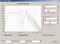
I just downloaded the latest update # 3930-150729. When I tried running a simulation for a T-TQWT in driver arrangement TH. I noticed, that in the Wizard double-clicking on the Frequency does not change the range, is that because THs usually are only used in the low frequency range? I like your scale moving suggestion from Post # 5639, but I'm like Mark in Post #5641.
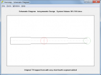
Then I tried to add a very short 4th segment setting S5=S4, flare same as segment 3, and L45 (now Par) to 0.01. The result just looks wrong, and it is not the same result I get when adding just 0.01 to L34 (which basically does not change the simulation result at all). I would have expected that setting S5=S4 and L45=0.01 would give a similar result. Maybe a bug?
Regards,
Hi David,
Thanks for the bug fixes.
I just downloaded the latest update # 3930-150729. When I tried running a simulation for a T-TQWT in driver arrangement TH. I noticed, that in the Wizard double-clicking on the Frequency does not change the range, is that because THs usually are only used in the low frequency range? I like your scale moving suggestion from Post # 5639, but I'm like Mark in Post #5641.
Then I tried to add a very short 4th segment setting S5=S4, flare same as segment 3, and L45 (now Par) to 0.01. The result just looks wrong, and it is not the same result I get when adding just 0.01 to L34 (which basically does not change the simulation result at all). I would have expected that setting S5=S4 and L45=0.01 would give a similar result. Maybe a bug?
Regards,
Attachments
Hi David,
Just disregard my last Post. I didn't switch to TH1. I'm the bug. (In the words of the poet: "Me so stupid!")
Regards,
Just disregard my last Post. I didn't switch to TH1. I'm the bug. (In the words of the poet: "Me so stupid!")
Regards,
Last edited:
Hi Oliver,
The answer is buried deep in the Loudspeaker Wizard section of the Help file:
"To change the frequency range, double-click on the chart frequency label. Not applicable when absorbent filling material is included."
The reason for not allowing the 100Hz to 20000Hz range to be shown when filling is specified is because the absorbent material model breaks down numerically at higher frequencies, giving invalid results. See Post #3924 linked below for further information.
http://www.diyaudio.com/forums/subwoofers/119854-hornresp-393.html#post3747637
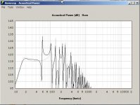
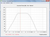
After posting my message yesterday, I thought about it more deeply and realised that changing the dB range would probably not be of much use anyway, because depending upon the peaks in the response, the chart already shows levels down to 30 to 40 dB below the level at the lower rolloff frequency, which should be low enough - anything at that level is not going to be of material significance. As can be seen from Attachment 1, for very low frequency horns, the level at 10Hz will be shown anyway.
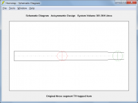
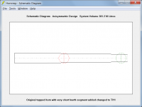
Adding a fourth segment to a TH tapped horn shifts the second entry point from S3 to S4, which is why the result you are getting is so different. If you change the four segment system from TH to TH1 the S4 entry point will move back from S4 to S3, and the result will be virtually identical to the original one, as expected. If you check the schematic diagrams for the different cases, the differences will be immediately obvious. Attachments 2 (original) and 4 (TH1) are effectively the same, whereas Attachment 3 (4 segment TH) is quite different.
From the Tapped Horn section of the Help file:
"Driver entry points are at S2 and S3 for a three segment TH horn, S2 and S4 for a four segment TH horn, and S2 and S3 for a four segment TH1 horn."
Many thanks for the feedback. Even though this time there were no new bugs to fix, there could have been. I really appreciate you taking the time to report back your concerns when you see something that doesn't seem right.
Kind regards,
David
I noticed, that in the Wizard double-clicking on the Frequency does not change the range, is that because THs usually are only used in the low frequency range?
The answer is buried deep in the Loudspeaker Wizard section of the Help file:
"To change the frequency range, double-click on the chart frequency label. Not applicable when absorbent filling material is included."
The reason for not allowing the 100Hz to 20000Hz range to be shown when filling is specified is because the absorbent material model breaks down numerically at higher frequencies, giving invalid results. See Post #3924 linked below for further information.
http://www.diyaudio.com/forums/subwoofers/119854-hornresp-393.html#post3747637
I like your scale moving suggestion from Post # 5639, but I'm like Mark in Post #5641.
After posting my message yesterday, I thought about it more deeply and realised that changing the dB range would probably not be of much use anyway, because depending upon the peaks in the response, the chart already shows levels down to 30 to 40 dB below the level at the lower rolloff frequency, which should be low enough - anything at that level is not going to be of material significance. As can be seen from Attachment 1, for very low frequency horns, the level at 10Hz will be shown anyway.
Then I tried to add a very short 4th segment setting S5=S4, flare same as segment 3, and L45 (now Par) to 0.01. The result just looks wrong, and it is not the same result I get when adding just 0.01 to L34 (which basically does not change the simulation result at all). I would have expected that setting S5=S4 and L45=0.01 would give a similar result.
Adding a fourth segment to a TH tapped horn shifts the second entry point from S3 to S4, which is why the result you are getting is so different. If you change the four segment system from TH to TH1 the S4 entry point will move back from S4 to S3, and the result will be virtually identical to the original one, as expected. If you check the schematic diagrams for the different cases, the differences will be immediately obvious. Attachments 2 (original) and 4 (TH1) are effectively the same, whereas Attachment 3 (4 segment TH) is quite different.
From the Tapped Horn section of the Help file:
"Driver entry points are at S2 and S3 for a three segment TH horn, S2 and S4 for a four segment TH horn, and S2 and S3 for a four segment TH1 horn."
Many thanks for the feedback. Even though this time there were no new bugs to fix, there could have been. I really appreciate you taking the time to report back your concerns when you see something that doesn't seem right.
Kind regards,
David
Attachments
Just disregard my last Post.
Hi Oliver,
Too late - I posted my reply before I noticed your new message 🙂.
Kind regards,
David
Hi David,
Thanks for taking your time, and looking into this. I woke up in the middle of the night thinking, you didn't do this did you? Too many irons in the fire, too much fun, oh well. 🙂
Regards,
Thanks for taking your time, and looking into this. I woke up in the middle of the night thinking, you didn't do this did you? Too many irons in the fire, too much fun, oh well. 🙂
Regards,
I woke up in the middle of the night thinking,
I do that all the time, unfortunately - I have great trouble "switching off" 🙂.
I didn't understand what your constraints within the program were David.
Hi Mark,
The constraints are self-inflicted, but I do have my reasons 🙂.
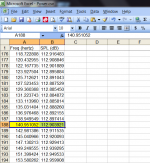
The number of frequency data points between 10Hz and 20000Hz is fixed at 533 so that:
1. The frequencies at points 1, 162, 323 and 484 are exactly 10Hz, 100Hz, 1000Hz and 10000Hz respectively. I do like things to be neat 🙂.
2. For the default 100% magnification display setting of 96 pixels per inch, and with the chart size used in Hornresp, there is a frequency data point at each pixel position, meaning that maximum frequency resolution is obtained.
The frequencies actually used can be seen by exporting the chart data, or by clicking the mouse on a chart (the frequencies are the same for the same data point in the list or on the screen, allowing for rounding).
The width of a Loudspeaker or Filter Wizard chart is the exactly the same as the distance from 10Hz to 2000Hz or from 100Hz to 20000Hz on the main chart, so that the frequency and pixel points match identically in all charts.
As you can see, the magic number of 533 data points in Hornresp is no arbitrary choice 🙂.
Kind regards,
David
Attachments
I don't know if this is really worthy of a feature request, but I was thinking it might be cool to have a way to vary S1-S5 with some slider by the same proportion. Imagine for example a tapped horn with par segments. You'd effectively be using the slider to change the cabinet width without affecting the expansion/internal fold style. This is also useful for FLH too. Like, for example, BFM sub plans (not that I really like them) have horns that have the same internal layout that you can make with a number of widths for different efficiencies and low corners. A way to vary all the horn segments by the same proportion would let you sim the different widths quickly.
Not sure if that's a really good explanation, but it's something I've thought might be very useful on numerous occasions.
Not sure if that's a really good explanation, but it's something I've thought might be very useful on numerous occasions.
I like the idea. I didn´t spent much time thinking about it, but instantly one example came tom my mind: If designing a Subwoofer with one driver and then wanting to do the same cab with two or more drivers would be a case where this is useful, too.
Of course I can simply double the values by hand or do a quick check up by simulating two or more cabs.
Of course I can simply double the values by hand or do a quick check up by simulating two or more cabs.
Hi zettairyouiki,
I like the idea for Post #5649, right now I do this in a spreadsheet, and then transfer the numbers into the Hornresp Input window. Lots of time, steps and places to make errors. A common width slider would be great for all the 1/4 wave boxes.
Regards,
I like the idea for Post #5649, right now I do this in a spreadsheet, and then transfer the numbers into the Hornresp Input window. Lots of time, steps and places to make errors. A common width slider would be great for all the 1/4 wave boxes.
Regards,
I was thinking it might be cool to have a way to vary S1-S5 with some slider by the same proportion.
Hi zettairyouiki,
Finding room in the Loudspeaker Wizard to include a width slider might be a bit of a challenge, depending upon the number of segments specified. Also, I am not sure what it would mean to have the values of all the area sliders changing as a result of the width slider being altered.
I will have to give it some further thought 🙂.
Kind regards,
David
Width Slider in Loudspeaker Wizard
Hi zettairyouiki and Interested Others,
I have found a suitable location for the width slider.
It should be possible to satisfactorily control the interactions between the width and area sliders.
Q1. In addition to the area sliders, should the value of the Vrc slider also change when the width slider is altered?
Q2. Presumably the values of the Vtc, Atc, Ap and Ap1 sliders should not change when the width slider is altered. Does everyone agree with this approach?
Kind regards,
David
Hi zettairyouiki and Interested Others,
Finding room in the Loudspeaker Wizard to include a width slider might be a bit of a challenge, depending upon the number of segments specified.
I have found a suitable location for the width slider.
Also, I am not sure what it would mean to have the values of all the area sliders changing as a result of the width slider being altered.
It should be possible to satisfactorily control the interactions between the width and area sliders.
Q1. In addition to the area sliders, should the value of the Vrc slider also change when the width slider is altered?
Q2. Presumably the values of the Vtc, Atc, Ap and Ap1 sliders should not change when the width slider is altered. Does everyone agree with this approach?
Kind regards,
David
Hi David,
I feel the approach you suggest in Post #5657 will work, just the major cross-sectional areas, and if used the Vrc, should change simultaneously w/ a width slider.
Regards,
I feel the approach you suggest in Post #5657 will work, just the major cross-sectional areas, and if used the Vrc, should change simultaneously w/ a width slider.
Regards,
I agree that it makes sense to tie VRC in as well. Logic would dictate that gets changed with changing the width. I think it makes much more sense to possibly have to tweak VRC after adjusting the width than having to keep updating VRC manually as you play with the width.
- Home
- Loudspeakers
- Subwoofers
- Hornresp