what are the odds of that😎If you want to keep the driver, you should use System Design/With Driver. System Design From Specification also calculates driver parameters, but I have never seen a case where only Mmd changes. Usually other driver parameters change as well.
Regards,
Bjørn
if you could only change the mmd,you have the perfect driver🙂
That's why I couldn't quite believe this.
Hi Oliver,
It seems that you must have picked an almost optimal driver to start with 🙂. The chances of doing this would be quite remote, I expect - a bit like getting a hole in one in golf...
Kind regards,
David
Hi,
That's why I couldn't quite believe this.
Regards,
Are you talking about this driver?
http://www.parts-express.com/pdf/264-332.pdf
I think you've entered the specs incorrectly, I get this...
Attachments

David, I'd like to request that the wavefront simulator show its output over a wider window (graphical window), preferrably one that I could set myself and then retain as standard between a set of comparisons so I could see the wave travelling further outward. (Even a hex location would be helpful if possible).
I'd like to ask while I'm here your usage of the term isophase in the help notes regarding the wavefront simulator. Is this indicating a limitation or does it simply mean the source is assumed to be free of non-linear effects?
I'd like to ask while I'm here your usage of the term isophase in the help notes regarding the wavefront simulator. Is this indicating a limitation or does it simply mean the source is assumed to be free of non-linear effects?
David, I'd like to request that the wavefront simulator show its output over a wider window (graphical window), preferrably one that I could set myself and then retain as standard between a set of comparisons so I could see the wave travelling further outward. (Even a hex location would be helpful if possible).
I'd like to ask while I'm here your usage of the term isophase in the help notes regarding the wavefront simulator. Is this indicating a limitation or does it simply mean the source is assumed to be free of non-linear effects?
Hi AllenB,
The purpose of the Hornresp Wavefront Simulator is simply to show how a perfect isophase wavefront will propagate down a given horn - it is not really intended to be used as a design tool. In practice, wavefronts will not necessarily be purely isophase, because of the different modes of vibration generated within the horn.
There is probably little to be gained by showing the isophase wavefronts extending much beyond the mouth of the horn, as the actual wavefronts generated by the horn will be somewhat different.
A far more sophisticated finite element analysis tool than the Hornresp Wavefront Simulator would be required to accurately show wavefront pressure and phase contours.
Kind regards,
David
Thank you for clearing that up. So, within the horn formula capabilities and statistical limitations in the treble...
I find the spectrogram simpler than the wavefront simulator for finding the mouth termination backwave. Would there be an infinite baffle option outside of the wavefront simulator?
I find the spectrogram simpler than the wavefront simulator for finding the mouth termination backwave. Would there be an infinite baffle option outside of the wavefront simulator?
Would there be an infinite baffle option outside of the wavefront simulator?
You can draw your own walls with the mouse in the wavefront simulator. I think the baffle will behave as if it was infinite if you extend the wall to the edge of the window.
Regards,
Bjørn
q
why is the responce graph so different in akabak?
i exported the data in to akabak,and i get much more hf output ,see pic.
why is the responce graph so different in akabak?
i exported the data in to akabak,and i get much more hf output ,see pic.
Hello,
H = 0° and V =0° on the Akabak graph mean that the displayed response is "on axis".
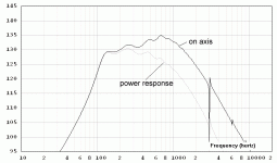
Now, if in Hornresp, we approximate your horn as being an exponential horn with a cut-off of 182,86Hz and a length of 40,64cm then we can display both the power response and the on axis response. See attached graph :
As you can see, the difference between the HornResp simulation and the Akabak simulation is very small indeed.
Best regards from Paris, France
Jean-Michel Le Cléac'h
H = 0° and V =0° on the Akabak graph mean that the displayed response is "on axis".
Now, if in Hornresp, we approximate your horn as being an exponential horn with a cut-off of 182,86Hz and a length of 40,64cm then we can display both the power response and the on axis response. See attached graph :
As you can see, the difference between the HornResp simulation and the Akabak simulation is very small indeed.
Best regards from Paris, France
Jean-Michel Le Cléac'h
Attachments
It's due to graph scaling on the horizontal axis. Make the graphs go to the same scale and it will look the same.
tnx jean-michel
all is clear now
to bad the directivety function is not available for a conical ,multisection horn.
all is clear now
to bad the directivety function is not available for a conical ,multisection horn.
Horn design
Hello All,
I am new in audio design. I would appreciate any help or critics of my Hornresp calculations and folded horn.
Regards,
V22


Hello All,
I am new in audio design. I would appreciate any help or critics of my Hornresp calculations and folded horn.
Regards,
V22
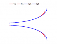
Hi to all : which function of hornresp is capable of calculating true spherical wave horns ? Mathematically there is a difference between a tractrix and a spherical. Are there striking differences between the spherical and the Le Cléac'h or Tractrix horn in overall sound, frequency range, loading, beaming at higher frequencies etc ?
which function of hornresp is capable of calculating true spherical wave horns ?
Hi Chano,
There is no separate function as such. Simply specify the flare profile as Sph.
Kind regards,
David
Attachments

Hello David, Thank You. I am using hornresp 29.10. It allows only Par-Exp-Con. How can I access the parameter Sph ? Do I need a particular configuration of other fields ? I dumbly copied your values but did not succeed (error : AT must be greater than Fta, but you have FTA 88.28 and AT 4.67). Are you using a secret HR version ? PS Your horndata files in another thread were very helpful too. And : does a spherical profile differ soundwise from a tractrix ?
To select Hyp, Lec, Obl, Sph or Tra flare in edit mode, press H, L, O, S or T when the L12 length parameter has the focus. "I overlooked that one" & "it actually works".
does a spherical profile differ soundwise from a tractrix ?
Hi Chano,
While I have no practical experience with either spherical wave or tractrix horns, it would seem from the theory that there should be little difference in the SPL responses, as the throat impedance characteristics of the two horns are very similar. It is only near the mouth that the profiles vary.
There may be subtle differences in the directivity patterns at higher frequencies, but not enough to really matter.
The most important thing from a practical standpoint is that for a given throat area and flare cutoff frequency, a full-mouth spherical wave horn will always be physically larger than a full-mouth tractrix horn - see the attached comparison.
Kind regards,
David
Attachments
- Home
- Loudspeakers
- Subwoofers
- Hornresp