O.K., it looks like you guys are sleeping in today. I will take a stab at the first question "If I was to explain acoustic impedance to my six year old grandson, what would I say?" The kids is actually very smart, so there may be hope.
"Now listen boy, there is something called electrical resistance, and something called acoustic resistance, and they are very different.
Electrical impedance is like a resistance or opposition to the voltage that is passing through the driver. Now that driver right there that says 8 ohms on the back, but is only actually an average of 8 ohms. If you picked two different frequencies and tested it, it would likely be vastly different measurements.
Now acoustic impedance is based on what is going on inside of the cabinet that driver is in. At certain frequencies, certain things will happen to cause more resistance or opposition, and that will effect the way the cabinet sounds and behaves. In a tapped horn, the sound has a long way to travel, so acoustic impedance is something you better pay attention to.
So boy, don't ask me any more questions right now, and how about you go outside and shovel some snow."
SO IS GRANDPA TELLING LIES AGAIN?
Last edited:
Hi Y'all,
I know all of you know better, but just to keep things from getting confusing, Post #77: "...When it comes to the L34 distance, or the L45 distance (driver acoustic center to throat)..." That should read, driver acoustic center to mouth (not throat).
As to impedance measurements, I know I was, and I think littlemike and epa were also referring to the driver's electrical impedance when installed in the enclosure.
Vance Dickason's Loudspeaker Design Cookbook would be very helpful here, and should be on every speaker builders book shelf: Loudspeaker Design Cookbook 7th Edition Book | 500-035 I highly recommend it, he describes the methods used for measuring impedance, as well as measuring and calculating Thiel/Small parameters of your driver. Then there are various test and measurement systems: SPL Meters / Audio Analyzers in the Speaker Components Department at Parts Express | 337 (I'm lusting for the OmniMic Precision Measurement System, but, sofar have been to cheap. 🙂)
Brian Steele has a nice page/example on using impedance graphs in a tapped horn: The Subwoofer DIY Page v1.1 - Projects : Using Impedance Graphs
As to acoustic impedance for your 6 year old grandson, maybe the simple air resistance when moving paddles of different size (e.g.: 6"x6" and 18"x18"), and seeing how fast he can move them?
Regards,
So boy, don't ask me any more questions right now, and how about you go outside and shovel some snow."
SO IS GRANDPA TELLING LIES AGAIN?
Depends on the locale......... around here it's 'rake the leaves'. 😀
GM
O.K. Oliver - It looks like I was telling lies, propagating ideas that have no basis in reality. Bad Grandpa.
The good news is that I believe I actually may have an early edition of The Loudspeaker Cookbook stashed away in the basement. I bought a bunch of books when I was younger and I think that was one that was too scientific for me at that point in my life. And since I have become interested in speaker design more recently, I never bothered to find it - I had assumed it had outdated info. I will try and dig that out tonight, it may be the source of information that will clear up my confusion in numerous areas. Thanks for the recommendation.
I actually have some speakers testing equipment already. I have never done much subwoofer testing though, I have used it manly for PA tops and home stereo speakers. I really like building crossovers and tweaking them to perfection, and that is what I have used it for up to this point.
Thanks for the Brian Steele article too. That is exactly what I need. Thanks for your help.
Last edited:
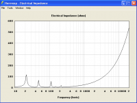
Impedance measurements are as valuable as (if not even moreso than) SPL.
+1
Dayton PA385S-8 TH simmed example:
GM
Attachments
+1
Dayton PA385S-8 TH simmed example:
GM
GM, I had already imported your HR file from post #45. When I check the Electrical Impedance, I get a very different graph than the one you just put up in post #85. Any idea what I could be doing wrong?
Attachments
Sorry, it's a different alignment meant to 'prove' that the impedance sim trumps its SPL sim, but changed my mind in midstream only to find I had inadvertently posted what I'd started. I'm always in a hurry with little time for the forums or PMs anymore, so anything longer than a one-liner from me has usually been done in bits n' pieces over time.
Since it's up though, its a good one to reverse engineer. 😉
GM
Since it's up though, its a good one to reverse engineer. 😉
GM
Hi Y'all,
I know all of you know better, but just to keep things from getting confusing, Post #77: "...When it comes to the L34 distance, or the L45 distance (driver acoustic center to throat)..." That should read, driver acoustic center to mouth (not throat).
As to impedance measurements, I know I was, and I think littlemike and epa were also referring to the driver's electrical impedance when installed in the enclosure.
Vance Dickason's Loudspeaker Design Cookbook would be very helpful here, and should be on every speaker builders book shelf: Loudspeaker Design Cookbook 7th Edition Book | 500-035 I highly recommend it, he describes the methods used for measuring impedance, as well as measuring and calculating Thiel/Small parameters of your driver. Then there are various test and measurement systems: SPL Meters / Audio Analyzers in the Speaker Components Department at Parts Express | 337 (I'm lusting for the OmniMic Precision Measurement System, but, sofar have been to cheap. 🙂)
Brian Steele has a nice page/example on using impedance graphs in a tapped horn: The Subwoofer DIY Page v1.1 - Projects : Using Impedance Graphs
As to acoustic impedance for your 6 year old grandson, maybe the simple air resistance when moving paddles of different size (e.g.: 6"x6" and 18"x18"), and seeing how fast he can move them?
Regards,
Oopsies...
I even proof-read it, still missed that. Sorry if I caused any confusion, I meant "mouth".
And - I was referring to electrical impedance.
Since it's up though, its a good one to reverse engineer. 😉GM
O.K GM, I will accept your challenge. Let's make sure we are on the same page though.
Is the chart you made in post #85 created from the HR export you attached to post #45, with some changes to it? If that is correct, I believe I have replicated the what you did to achieve that result. After playing with the different parameters, all I had to do was shorten L23 to 80cm, and the results appear very similar. But that had a drastic effect on the SPL chart. The results are posted below.
Attachments
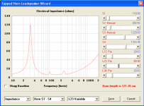
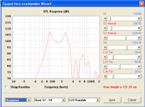
Well, I did mine using a [T]horn design routine, so it's different in detail, but not the alignment concept. Since it looks way too under-damped, it would likely not be considered a viable alignment, yet the impedance plot indicates otherwise.
GM
GM
Last edited:
Experiment #2 - Tally Skinny Flat Fifteen (TSF15)
Hey, that title reminds me of my first girlfriend, but that another story . . . .
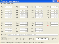
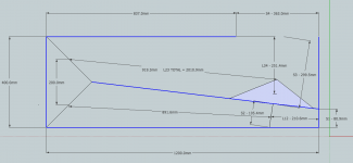
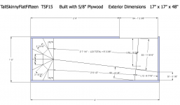
Here is my latest experiment, the TSF15. It looks to me like this design would get about 125dB with 300 watts (50Volts). Using 1/2” plywood, the footprint is about 17” x 17” x 48". The internal width is 400mm. The driver is the PRV Audio 15W1600 PA Woofer: PRV Audio 15W1600 15" High Power PA Woofer 8 Ohm | 294-2742
I taught myself a bit of Google SketchUp today, so also included in this presentation is what I hope is a fairly accurate drawing. So, if any of you want to take a look at this design and tear it apart, I would really appreciate you opinions.
Hey, that title reminds me of my first girlfriend, but that another story . . . .
Here is my latest experiment, the TSF15. It looks to me like this design would get about 125dB with 300 watts (50Volts). Using 1/2” plywood, the footprint is about 17” x 17” x 48". The internal width is 400mm. The driver is the PRV Audio 15W1600 PA Woofer: PRV Audio 15W1600 15" High Power PA Woofer 8 Ohm | 294-2742
I taught myself a bit of Google SketchUp today, so also included in this presentation is what I hope is a fairly accurate drawing. So, if any of you want to take a look at this design and tear it apart, I would really appreciate you opinions.
Attachments
Hi DHAA,
Just real briefly: looks good. You might review the "advanced centerline method" (hint: this ain't it). Have you take the wall thicknesses into account?
I think you're on your way.
Regards,
Just real briefly: looks good. You might review the "advanced centerline method" (hint: this ain't it). Have you take the wall thicknesses into account?
I think you're on your way.
Regards,
You might review the "advanced centerline method" (hint: this ain't it). Have you take the wall thicknesses into account?
Hey, thanks. I realize I didn't use the advanced centerline method, but by that point I was getting pretty frustrated with SketchUp. Maybe tomorrow I will read the manual and see what I can learn. Same thing, with the wall thickness, at this point it is just an idea that I need to fine tune.
I am still struggling with the concept of electrical impedance. I have been doing some reading on that subject, but either there seems to be some conflicting opinions, or I am still not fully grasping the idea. Any comments on the electrical impedance results on this build? Thanks
Hi DHAA,
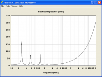
Look @ an impedance graph of the driver in a big sealed enclosure, that's basically your baseline. Then note the differences between that one, and the tapped horn's impedance graph.
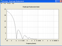
Look at the impedance graph together w/ the displacement graph, for every impedance peak you get an area of large displacement, for every impedance trough you get an area of minimal displacement. Can you correlate the distance between the driver's front and back side, and the other distances in acoustical terms w/ the peak locations (frequencies)?
Then look at them again while reading "The Tapped and Synergy Horn Explained" white paper @ White Papers | Danley Sound Labs | Danley Sound Labs, Inc.
You are making good progress, pretty soon we'll be asking you questions. 🙂
Regards,
Look @ an impedance graph of the driver in a big sealed enclosure, that's basically your baseline. Then note the differences between that one, and the tapped horn's impedance graph.
Look at the impedance graph together w/ the displacement graph, for every impedance peak you get an area of large displacement, for every impedance trough you get an area of minimal displacement. Can you correlate the distance between the driver's front and back side, and the other distances in acoustical terms w/ the peak locations (frequencies)?
Then look at them again while reading "The Tapped and Synergy Horn Explained" white paper @ White Papers | Danley Sound Labs | Danley Sound Labs, Inc.
You are making good progress, pretty soon we'll be asking you questions. 🙂
Regards,
Wow, thanks Oliver. I think I am beginning to understand. Nice explanation, it helped to clear up some confusion I was having - I was kind of thinking of it backwards - higher impedance (resistance) would reduce efficiency. O.K., now I think I see the light. That Danley paper you posted looks good too, I will have to study that a bit.
I am working on a new SketchUp drawing today whenever I get time. It is looking a lot better than the one I posted yesterday.
I sure have learned a lot since you guys have started helping me. But I am learning so fast I am having a hard time keeping track of it all. Albert Einstein once said "Any fool can know. The point is to understand." I am still the fool, trying hard to understand. Thanks for your help.
I am working on a new SketchUp drawing today whenever I get time. It is looking a lot better than the one I posted yesterday.
You are making good progress, pretty soon we'll be asking you questions. 🙂
I sure have learned a lot since you guys have started helping me. But I am learning so fast I am having a hard time keeping track of it all. Albert Einstein once said "Any fool can know. The point is to understand." I am still the fool, trying hard to understand. Thanks for your help.
Here is my latest drawing of the TSF15, along with the new HR data export.
Known problems:
- I couldn't get the baffle board drawn in correctly with the proper angle and thickness, so it is just a single line. To make up for this, I calculated S1-S3 as if there was a 5/8" baffle board in place.
- The acoustic center of the driver for the L34 calculation is just an estimate.
Questions:
- Do I have the right idea for the Advanced Centerline Method?
- Do I have the right idea for calculating L34 for a front firing horn using the Acoustic Center of the Driver method?
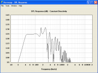
- I optimized this design for the flattest frequency response I could get in the pass band. I am still experimenting with ideas how Electrical Impedance and Driver Displacement are effected by the horn design, so if anyone see's problems with what I have going on here, please let me know.
Known problems:
- I couldn't get the baffle board drawn in correctly with the proper angle and thickness, so it is just a single line. To make up for this, I calculated S1-S3 as if there was a 5/8" baffle board in place.
- The acoustic center of the driver for the L34 calculation is just an estimate.
Questions:
- Do I have the right idea for the Advanced Centerline Method?
- Do I have the right idea for calculating L34 for a front firing horn using the Acoustic Center of the Driver method?
- I optimized this design for the flattest frequency response I could get in the pass band. I am still experimenting with ideas how Electrical Impedance and Driver Displacement are effected by the horn design, so if anyone see's problems with what I have going on here, please let me know.
Attachments
While I understand that you we're actually mistakenly asking about acoustical impedance, while the other posters were referring to electrical, I think the acoustical impedance is an interesting/useful concept too, and merits some explanation. It helps to understand sensitivity/efficiency, and why it becomes increasingly hard to build speakers with more than 103 or so dB sensitivity.
Actually, electrical impedance and acoustical impedance are quite analogous. When I learned about acoustical impedance it actually helped me to understand electrical impedance better.
I know of 3 types of impedance (and there are surely more used in other fields): electrical, mechanical and acoustical. All of then can be described as simple A/B quotients. This can be thought of as "how much A to I need to achieve a desired amount of B in this material?"
-So, electrical impedance is V/I - in other words "how much voltage do I need to apply to make a certain current flow through this impedance?"
-Mechanical impedance is F/v - that means "how much force to I need to apply to this object for it to move at a certain velocity?"
-And acoustical impedance is simply mechanical impedance divided by area. And as you may know, force divided by area is pressure. So acoustic impedance can be expressed as p/v - "how much pressure do I need to apply to these particles to make them move at a certain velocity?"
As you can see, the descriptions are quite analogous, and the similarities don't end there. In electrical circuits, if you instead of dividing, multiply V*I you get the electrical power. For acoustics this is similar, if you multiply p*v you get the acoustic intensity (this is similar to the acoustic power, but not quite, because it is actually power/area, because if you radiate your acoustic power into a bigger area, the intensity at each spot will be lower - this should be intuitively clear).
SPL (in dB) by the way is basically just acoustic intensity, except displayed as a logarithmic value instead of a linear one (well, actually there are several different ways of calculating your decibels, but in normal temperatures and air pressures the resulting values should all be the same).
And finally, to find out what is interesting about acoustical impedance you need to consider how impedance affects power transfer in electrical circuits. All real electrical devices have non-zero input or output impedance. And when you connect an input to an output, the voltage divider created by the two impedances will determine how much power is transferred to the target device, and how much is "wasted." So what you want to do is match these impedances as well as possible to ensure optimal power transfer.
For acoustical impedance this is the same - it's hard to transfer acoustic energy from a material with one impedance into one with a vastly different impedance. This is why when you are underwater you have a hard time hearing what somebody above water is saying, because the acoustical impedances of air and water differ by about 3 orders of magnitude. This is also the reason why small speaker drivers won't play very loud/efficiently - because the impedance is not well matched with the air, and thus often less than 0.1% of the electrical power (that's about 82dB / 1V / 1m, btw) you're sending in makes it out. And just like in electrical circuits you can fix an impedance mismatch by using a transformer, there are also acoustical transformers that will transform your output impedance to something better matched to free air - we call these output transformers "horns."
"Now listen boy, there is something called electrical resistance, and something called acoustic resistance, and they are very different."
SO IS GRANDPA TELLING LIES AGAIN?
Actually, electrical impedance and acoustical impedance are quite analogous. When I learned about acoustical impedance it actually helped me to understand electrical impedance better.
I know of 3 types of impedance (and there are surely more used in other fields): electrical, mechanical and acoustical. All of then can be described as simple A/B quotients. This can be thought of as "how much A to I need to achieve a desired amount of B in this material?"
-So, electrical impedance is V/I - in other words "how much voltage do I need to apply to make a certain current flow through this impedance?"
-Mechanical impedance is F/v - that means "how much force to I need to apply to this object for it to move at a certain velocity?"
-And acoustical impedance is simply mechanical impedance divided by area. And as you may know, force divided by area is pressure. So acoustic impedance can be expressed as p/v - "how much pressure do I need to apply to these particles to make them move at a certain velocity?"
As you can see, the descriptions are quite analogous, and the similarities don't end there. In electrical circuits, if you instead of dividing, multiply V*I you get the electrical power. For acoustics this is similar, if you multiply p*v you get the acoustic intensity (this is similar to the acoustic power, but not quite, because it is actually power/area, because if you radiate your acoustic power into a bigger area, the intensity at each spot will be lower - this should be intuitively clear).
SPL (in dB) by the way is basically just acoustic intensity, except displayed as a logarithmic value instead of a linear one (well, actually there are several different ways of calculating your decibels, but in normal temperatures and air pressures the resulting values should all be the same).
And finally, to find out what is interesting about acoustical impedance you need to consider how impedance affects power transfer in electrical circuits. All real electrical devices have non-zero input or output impedance. And when you connect an input to an output, the voltage divider created by the two impedances will determine how much power is transferred to the target device, and how much is "wasted." So what you want to do is match these impedances as well as possible to ensure optimal power transfer.
For acoustical impedance this is the same - it's hard to transfer acoustic energy from a material with one impedance into one with a vastly different impedance. This is why when you are underwater you have a hard time hearing what somebody above water is saying, because the acoustical impedances of air and water differ by about 3 orders of magnitude. This is also the reason why small speaker drivers won't play very loud/efficiently - because the impedance is not well matched with the air, and thus often less than 0.1% of the electrical power (that's about 82dB / 1V / 1m, btw) you're sending in makes it out. And just like in electrical circuits you can fix an impedance mismatch by using a transformer, there are also acoustical transformers that will transform your output impedance to something better matched to free air - we call these output transformers "horns."
Wow, James, thanks for that post. The level on knowledge on this forum is amazing. Your examples were very helpful, reminding me of various EE and physics concept I didn't think would ever use again.
And I see you are from Germany. I believe Albert Einstein who, I mentioned above, was born in Germany. You might want to check your family tree as he might be your great grandpa. It sound like you are someone who "understands."
Thanks very much for taking the time to post that information. The fog in my mind is starting to clear! I printed out you post and hung it on the wall next to Oliver's (tb46's) AutoCAD drawing of my first tapped horn design.
That is my new motto.
And I see you are from Germany. I believe Albert Einstein who, I mentioned above, was born in Germany. You might want to check your family tree as he might be your great grandpa. It sound like you are someone who "understands."
Thanks very much for taking the time to post that information. The fog in my mind is starting to clear! I printed out you post and hung it on the wall next to Oliver's (tb46's) AutoCAD drawing of my first tapped horn design.
And just like in electrical circuits you can fix an impedance mismatch by using a transformer, there are also acoustical transformers that will transform your output impedance to something better matched to free air - we call these output transformers "horns."
That is my new motto.
Hi again,
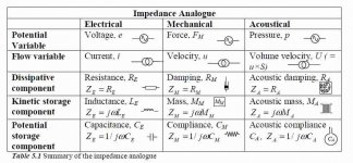
I also like jwmbro's explanation very much. I'll attach an Impedance Analogue chart, and a pdf for your wall.
You are making good progress at Sketchup, NEO Dan pointed me to some nice sketchup tutorials: Sketchup for Woodworkers - Home Good tutorials, but I'm just too stuck on AutoCAD, maybe I'll give it another try one of these days.
As to your questions: yes, you do have the correct centerline method in Post #96, and an estimate for the location of the acoustic center should be well close enough in this case; yes, L34 would be correct as shown.
One thing I noticed, is that you shortened S2 a little, I like to stay below a 3:1 compression ratio Sd=860.5cm^2 divide by 3 =286.83cm^2; I have seen people using up to 8:1, you better make sure that your driver can take that kind of abuse. I don't recommend it.
Regards,
Attachments
Hey Oliver, thanks once again.
Now that I am starting to get the hang of SketchUp, it is pretty fun to play around with. That "SketchUp for Woodworkers" link you provided is exactly what I was looking for. I spent a lot of time yesterday looking for some way to change the lines to represent the plywood thickness. Finally I realized you just use the 'rectangle tool' to make a long, thin rectangle of the proper dimensions. Duuuuuuuhhhhhhh!
Are you guys all engineer that dabble in speaker design for a hobby? The level of scientific knowledge involved in modern speakers design is mind boggling to me. If I didn't have a background in some of these areas from back in my younger days, it seems it would be almost unimaginable for someone to learn this stuff on their own.
Thanks for that Acoustic Quantities chart too, that will keep my mind busy for a while.
- Status
- Not open for further replies.
- Home
- Loudspeakers
- Subwoofers
- Hornresp Brainiacs - Help an Old Man