If you are familiar with any other good links explaining how fold a HR horn design into an actual cabinet, I would appreciate your recommendations.
I recommend that you do it the way I do it. Export the Horn Data and use csa vs length to draw it out on paper.
As I mentioned there are several other ways to get it done and there are resources all over the place. It would take quite a while to compile it all. And in good conscience I would have to explain which methods are better and which have flaws, and then talk about those issues in depth. This would take a lot more time than I have.
So I would prefer if you would pick a method that you would like to try and I will supply info for that specific method.
The link I provided was for a very specific purpose - it exposes the centerline vs advanced centerline methods and contains a lot of info about a lot of folding issues. Folding is a big topic and the more research you do the better off you will be. There are a lot of ways you can go astray during the folding process and that's a big reason why some people's sims don't match their measurements. Soho54 was probably the best resource for folding info I've ever seen but he's not around anymore. His work is featured several times and in several areas in the small study I linked to.
I have been using WinISD for ported cabs, I will have to try using Hornresp for that to gain more experience, especially since it would seem to be an easier and more accurate way to compare different models.
Practice, practice, practice. Most of people involved in this thread have hundreds of hours logged in to simulator experience. There are at least three different ways to simulate a ported box in Hornresp, some methods will be more accurate depending on the layout of the box.
Hi DHAA,
Just in case you want to build your original design, here is an updated and corrected drawing w/ the board dimensions and positions. I would probably relocate the mouth onto the side panel instead of the bottom, but that depends on your usage. Might be good practice to develop a new Hornresp simulation from the drawing.
Regards,
Attachments
Oliver - Wow, thanks! That is the most beautiful thing I have ever seen. I just printed it out and framed it. You are very good at this CAD thing.
That is a good idea to now convert that drawing back into Hornresp. I will try to work on that tomorrow.
That is a good idea to now convert that drawing back into Hornresp. I will try to work on that tomorrow.
GM, thanks for you input.
I am curious on your thought process when you came up with this design, so let state what I believe you may have been thinking, and please correct me if I am wrong.
You’re welcome!
Any resemblance to this way of designing a horn Vs how I do it would be strictly coincidental as I use Prof. Leach’s compression horn design routine, though of course there is a certain amount of, hmm… ‘interpretation’ required for tapped variants as outlined in Tom's DTS-20 patent.
Keep in mind though that I’ve only cloned the Jensen Transflex, an early ‘50s tapped TL, and several decades ago at that, so while my sims appear to line up well with the couple of Tom’s designs that details have been [briefly] published, I’ve no ‘hands on’ experience or feedback from any of the folks I’ve done sims for, so nothing to prove that my interpretation is necessarily the best one overall for squeezing out that last little bit of performance that gives a manufacturer at least a marketing edge if not an audible one.
Note too that there’s been some HR ‘slider’ sims that make no sense to me WRT speaker/horn design [and looked it], yet measured/performed well once damped and properly XO’d. Factor in digital EQ and there’s a lot of leeway in speaker/horn design nowadays, so simming the best you can get out of a net bulk/specific dims seems as good a way as any.
GM
Post #63
Hi DHAA,
...the most beautiful thing I have ever seen... That's funny, and you are welcome.
Regards,
Hi DHAA,
...the most beautiful thing I have ever seen... That's funny, and you are welcome.
Regards,
Question of the Day - Volume Displacement Calculations for Braces in TH
I have designed bass reflex cabinets before, and for those it was important to calculate the volume displacement of all braces, and then subtract that from the overall interior cabinet volume. If this was not done, the port tuning frequency would not be accurate.
For the tapped horn, there are no volume calculations. There are area calculations (S1-S5) but those are all done in areas where you would likely not be putting a brace.
So, is there any reason (or way) to take the volume displacement of braces into effect when designing a tapped horn? If so, how is it done?
Yes, you (should) subtract bracing from the interior volume like in any cabinet, brace material thickness x width x length.So, is there any reason (or way) to take the volume displacement of braces into effect when designing a tapped horn? If so, how is it done?
Yes, you (should) subtract bracing from the interior volume like in any cabinet, brace material thickness x width x length.
Thanks Art, but where does that apply to HR inputs? The "S" values are area calculations, at points there typically wouldn't be any bracing. The "L" values are lengths, which bracing would typically be running parallel to, so it shouldn't change the "L" value.
In my mind, I can see how the size of the bracing should affect the sound of the cab slightly, but I can't seem to figure out how you would input that into HR to model it correctly.
Hi DHAA,
I'm on vacation - yeah! In a little while I'll get to do some plumbing. Oh well.
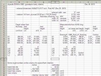
I make my self a spreadsheet (I still use Quattro Pro) to convert the cm to inches, and the duct areas to duct heights. It makes it real easy to add in whatever bracing to get a quick look. For most of the boxes for which I simulated the effect of bracing the difference was negligible. If you cut holes/openings into the braces it becomes even less important to calculate this.
I'll attach a screen shot of the one I made for your enclosure (I use the same basic template, thus I'll have tags hanging on that may or may not have anything to do with what I'm working on, e.g.: the front chamber and spacer volume at the bottom of this one. It beats starting over every time.).
When you subtract 2x left and right side thickness, and the thickness of the bracing material you end up w/ the internal width, this is used as a constant to divide the Hornresp areas, and to arrive at the duct heights. In this example I'm entering S1 into B17, convert it to in^2 in D17, and divide by the internal width constant from I8 in E17 to get the duct height in inches; same for the other areas.
I also have set up a calculation area where I enter the measurements from AutoCAD: enter duct height in H17, multiply w/ internal width constant in I17 for the area in in^2, convert to cm^2 in J17, divide by the internal width constant I9 (cm) in K17 to get the internal duct height in cm (don't need it, but may as well), then convert the height back to in as a control.
Probably just the poor mans way to do this, in some drafting environments you can automate all of this. I hope this helps,
Regards,
P.S.: Tried to check this post for errors, but you get what you paid for. 🙂
I'm on vacation - yeah! In a little while I'll get to do some plumbing. Oh well.
I make my self a spreadsheet (I still use Quattro Pro) to convert the cm to inches, and the duct areas to duct heights. It makes it real easy to add in whatever bracing to get a quick look. For most of the boxes for which I simulated the effect of bracing the difference was negligible. If you cut holes/openings into the braces it becomes even less important to calculate this.
I'll attach a screen shot of the one I made for your enclosure (I use the same basic template, thus I'll have tags hanging on that may or may not have anything to do with what I'm working on, e.g.: the front chamber and spacer volume at the bottom of this one. It beats starting over every time.).
When you subtract 2x left and right side thickness, and the thickness of the bracing material you end up w/ the internal width, this is used as a constant to divide the Hornresp areas, and to arrive at the duct heights. In this example I'm entering S1 into B17, convert it to in^2 in D17, and divide by the internal width constant from I8 in E17 to get the duct height in inches; same for the other areas.
I also have set up a calculation area where I enter the measurements from AutoCAD: enter duct height in H17, multiply w/ internal width constant in I17 for the area in in^2, convert to cm^2 in J17, divide by the internal width constant I9 (cm) in K17 to get the internal duct height in cm (don't need it, but may as well), then convert the height back to in as a control.
Probably just the poor mans way to do this, in some drafting environments you can automate all of this. I hope this helps,
Regards,
P.S.: Tried to check this post for errors, but you get what you paid for. 🙂
Attachments
Excellent bracing example as well as a more advanced TH to reverse engineer: Danley DTS-10 "Super Spud" DIY kit
GM
GM
Bonus Question
First off, thanks for your comments everyone. Now that I understand how the bracing is compensated for, I think I will ignore that temporarily until I get a better understanding of some other design elements that may have a greater effect on output. At least I feel better knowing the proper answer - that is one less thought rattling around in my head.
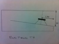
That brings up the Bonus Question. Please take a look at the two drawings I attached. The first one is the end firing TH design I used in my GBS15.
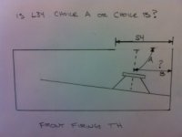
The second drawing is that cabinet converted to a front firing TH. My question here is does L34 need to be changed? Choice B would be calculating L34 the same way it was calculated in the end firing GBS15. Choice A would be recalculating L34 to the new horn mouth. The difference would be fairly small, is it worth worrying about?
Also, if choice A is the correct way to do it, I have one further question. Having the horn mouth on the front of the cabinet gives me room to play with the S4 dimension. Would the proper way to calculate L34 be to the center of the S4 opening? If so, it seems to me that changing S4 would also change L34 slightly. Thanks
First off, thanks for your comments everyone. Now that I understand how the bracing is compensated for, I think I will ignore that temporarily until I get a better understanding of some other design elements that may have a greater effect on output. At least I feel better knowing the proper answer - that is one less thought rattling around in my head.
I would probably relocate the mouth onto the side panel instead of the bottom, but that depends on your usage.
That brings up the Bonus Question. Please take a look at the two drawings I attached. The first one is the end firing TH design I used in my GBS15.
The second drawing is that cabinet converted to a front firing TH. My question here is does L34 need to be changed? Choice B would be calculating L34 the same way it was calculated in the end firing GBS15. Choice A would be recalculating L34 to the new horn mouth. The difference would be fairly small, is it worth worrying about?
Also, if choice A is the correct way to do it, I have one further question. Having the horn mouth on the front of the cabinet gives me room to play with the S4 dimension. Would the proper way to calculate L34 be to the center of the S4 opening? If so, it seems to me that changing S4 would also change L34 slightly. Thanks
Attachments
Last edited:
Hi DHAA,
Picture #2 would be the preferred method, much better access to the driver. As to the final size of the port opening I would stay w/ the same opening as originally designed. It's really hard to figure out what exactly is going on around the driver inside the duct w/ the front port, and how long is L34, do you measure it from the middle of the duct, or from the effective center of the diaphragm? It would also be easy to provide cleats so that an enlarged or a reduced size mouth can be installed, even a keystone if you want to play w/ that idea. Those cleats would also stiffen the port edges.
Regards,
Attachments
It's really hard to figure out what exactly is going on around the driver inside the duct w/ the front port, and how long is L34, do you measure it from the middle of the duct, or from the effective center of the diaphragm?
Neither of those drawings are proportional to the GBS15's dimensions. I just drew some generic horn shapes to give you guys a better understanding of what I was talking about.
At what point is it best to make the L34 measurement from?
Hi DHAA,
As I said above, there is no definite answer to that question, if someone would hold my feet to the fire I'd go w/ the effective center of the driver diaphragm, i.e.: 10.287 in the pdf above. Now you're at the point of build and measure, e.g.: how does the mouth size and location affect SPL and impedance? How close is the result to the simulation. Remember Tom Danley's advice: measurements trump simulations.
Regards,
Hey Oliver, thanks again. I think I may have mis-interpeted you comment "It's really hard to figure out what exactly is going on around the driver" as my drawing was unclear, buy maybe you meant it is unknown/unclear acoustically what really happens?
I have been looking over that spreadsheet you linked. I am starting to realize the more I learn, the less I really know. Tapped horn design is even a deeper subject that I had imagined. But I haven't been this excited about something for a while, so I guess it is good for me. Enjoy your vacation, and if you have any plumbing questions, don't be afraid to ask!
I have been looking over that spreadsheet you linked. I am starting to realize the more I learn, the less I really know. Tapped horn design is even a deeper subject that I had imagined. But I haven't been this excited about something for a while, so I guess it is good for me. Enjoy your vacation, and if you have any plumbing questions, don't be afraid to ask!
Hi DHAA,
Post #75:"...maybe you meant it is unknown/unclear acoustically what really happens?"
Yes, that's what I meant. One other way to approach this is to forget about the driver for a moment, and just draw the "advanced center line" from S1 to S4, then look at where the driver falls, call those two points S2 and S3, and the distance between them L23. Then what falls off at the ends is L12 and L34. Again, from reports from many different people you just move the port from the bottom to the front, and go on with it.
Look at the spreadsheet as a sophisticated legal pad, just easier once you get the hang of it. My main reason is all the back and forth between metric and imperial, and area v. duct height. Personally I don't care just wish the powers that be could agree on something (oh heck, what am I thinking).
Regards,
snip...
Remember Tom Danley's advice: measurements trump simulations.
DHAA,
Neat thread. Figured that I'd chime in here. Lots of great input in this thread, and I honestly didn't feel I had all that much to add until now.
Measurements for the win, period. Without data, you can't know what is going on. I can't stress this enough. Data is a fundamental.
I've developed my own "empirical" approach to folding and simulating, and my results get close to the models most of the time. When I don't, I can usually figure out why. Been there and done that. More than once.
When it comes to the L34 distance, or the L45 distance (driver acoustic center to throat), look for the shortest path, as that path length will yield the worst simulated results in most cases. If the worst case still looks decent, it might be sawdust worthy. Or, it might not. I've got personal experience (and the receipt for the fees at the local wood recycling facility) to back this up. Odds are, it won't measure that bad, it will fall somewhere between "ideal" and "worst case", but if you don't measure it, you won't ever know.
Impedance measurements are as valuable as (if not even moreso than) SPL. Both can be accomplished at a reasonable level of accuracy with free software and cheap hardware. If you want to buy tools to get it done, you're still looking at change from $200 for measurement capability that is just mind-boggling compared to what I used to do "back in the day". I may not be "that" old, but I've been mucking about making speakers for nearly 30 years now. My first measured response plots were done with an old tube audio generator I bought at a garage sale, an analog Radio Shack SPL meter, a pencil, and some graph paper.
If you measure your driver, then model with actual data, then translate that model into a set of plans and accurately build the cabinet, you should come close to matching your model.
i came to the same conclusion hereDHAA,
When it comes to the L34 distance, or the L45 distance (driver acoustic center to throat), look for the shortest path, as that path length will yield the worst simulated results in most cases.
Well littlemike, thanks for stoping by and helping hammer some new thoughts into my think skull.
Humm, that is an interesting thought. I need to realize that these simulations don't always truly represent reality. It would be easy to cheat and have great looking sims, but other than amusing myself, it would be meaningless.
That is a thought that has been rattling around in my head, which I don't have a full understanding off. Therefore, that will be the today's Question of the Day.
epa, thanks for chiming in - I can use all the help I can get. I will take a look at that link today. Thanks.
When it comes to the L34 distance, or the L45 distance (driver acoustic center to throat), look for the shortest path, as that path length will yield the worst simulated results in most cases. If the worst case still looks decent, it might be sawdust worthy.
Humm, that is an interesting thought. I need to realize that these simulations don't always truly represent reality. It would be easy to cheat and have great looking sims, but other than amusing myself, it would be meaningless.
Impedance measurements are as valuable as (if not even moreso than) SPL.
That is a thought that has been rattling around in my head, which I don't have a full understanding off. Therefore, that will be the today's Question of the Day.
epa, thanks for chiming in - I can use all the help I can get. I will take a look at that link today. Thanks.
Question of the Day - Acoustic Impedance in a TH
In post #77, littlemike mentioned impedance as being a very important factor in a design, and I believe was referring specifically to acoustic impedance. If my very limited understanding of this is correct, electrical impedance would purely be a driver factor, and the acoustic impedance would be the effect of that particular driver in a specific cabinet design. Any holes in my thinking so far?
So I decided to do a little research myself. Here is the definition of acoustic impedance I came across: "Mathematically, it is the sound pressure p divided by the particle velocity v and the surface area S, through which an acoustic wave of frequency f propagates."
Ouch, I have read that over and over trying to realize the how/what/who/why/where of applying this to a tapped horn design. I have actually put some thought into this previous to littlemike's comment, and there seems to be a missing link in my knowledge. I believe I can understand the relationship of "surface area S," but at this point in my journey I don't think can interpret the full definition.
[But hey, I really like that word "propagate" in the above definition. I am going to try to slip that into every conversation I have today. Already my wife suggested I go outside and shovel some snow. My retort was "I hereby propagate the idea that the snow is not going anywhere, and it will still be there if I do it later in the day." She had no comment, which is highly unusual.]
So, your mission, if you choose to accept it:
To attempt to simplify the concept of acoustic impedance and how it applies to a tapped horn design. Here are some ideas for explanation:
- If I was to explain acoustic impedance to my six year old grandson, what would I say?
- What would be the ideal acoustic impedance response I should strive for in my designs.
- What factors of a design have the biggest effect on acoustic impedance (both good and bad)?
- Why is acoustic impedance as important as SPL curve?
- Any other wisdom you would care to share.
Last edited:
- Status
- Not open for further replies.
- Home
- Loudspeakers
- Subwoofers
- Hornresp Brainiacs - Help an Old Man