The sims were done with ARPE from the FRD consortium. They have all kinds of nifty free tools. Most of them require Excel for Windows with the Analysis Toolpack and VBA installed (they aren't with a default Excel installation.)
http://www.pvconsultants.com/audio/radiation/arpe.htm
Edit: to mimic the directivity of the horn, I just told the program that the tweeter had a large diameter, adjusted until the off-axis response looked kinda like what I wanted. It really only works at one frequency and wouldn't work all the way up to 20K.
Dennis I tried that (big tweeter) but it's really not CD so I gave up. Wayne seems to have software that takes into account DI but he doesn't seem inclined to share what it is. That's the one downside to ARPE, otherwise it takes into account everything you could need.
SPEAK will do that problem and it even has a decent waveguide model. A large tweeter is nothing like a waveguide since one is spherical and the other planar wavefront. If I get a chance I'll try it, but in all honesty thats unlikely. I'm just swamped these days. No time for fun at all. DIY is the most fun I get - thats how pathetic my life is!!
Brandon, it seems to work okay on the polar plots for a single frequency but it doesn't work at all on the frequency response plots because the big tweeter doesn't mimic the horn's directivity as the frequency changes. I'm pretty confident that the polars I posted are accurate enough to give us a general idea of what's going on at the XO frequency. Certainly a lot better than a bunch of yak yak about general principles/philosophies with no specifics and no math (and I'm sure you agree). 😉
gedlee said:I'm just swamped these days. No time for fun at all. DIY is the most fun I get - thats how pathetic my life is!!
Dang, it's a b!tch having to work for a living, isn't it? 😉
catapult said:Certainly a lot better than a bunch of yak yak about general principles/philosophies with no specifics and no math (and I'm sure you agree). 😉
Agreed, but there is a significant difference in off axis amplitude and phase from a spherical source and a planar one and you haven't accounted for that. The -6 dB points can be made to match, but the rest will be entirely different. The use of a planar wavefront from a horn was a long time error in a lot of simulations because the real source is nothing like that. A real source is a much bigger problem to do however, so there is a reason for the common simplicity.
catapult said:
Here you go.
Thank you, Catapult.
From the polars, it appears to be the inverse of that, i.e., 10° up and 40° down, which makes sense considering the application; they are typically mounted above the audience listening height.
I can't tell you the actual offset of the acoustic centers, as I don't have any of these to measure, but in a similar pair I built for home, I found that moving the woofer back ~1" tilted the lobe too far downward; it played to the knees.
The filter was different, tho.
noah katz said:
*That's* a troll.
Nope, he said so, and when I quote that, you'll have yet another opportunity to apologize.
[Which is developing into somewhat of a trend here.... 😉 ]
ZilchLab said:From the polars, it appears to be the inverse of that, i.e., 10° up and 40° down, which makes sense considering the application; they are typically mounted above the audience listening height.
Ah, okay. That happens if you wire the drivers with reverse polarity. I had them wired with the same polarity in the sim. It doesn't really change the frequency response with a BW3 XO as they're in phase quadrature but it changes the lobing.
catapult said:
Ah, okay. That happens if you wire the drivers with reverse polarity. I had them wired with the same polarity in the sim. It doesn't really change the frequency response with a BW3 XO as they're in phase quadrature but it changes the lobing.
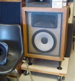
They're spaced a bit further apart, as well. The HF driver is BMS 4552nd, which several of you are studying.
I believe this qualifies as less yak-yak.
[OOPS, what's that on the chair there...? 😀 ]
Attachments
gedlee said:I completely agree that the crossover dominates the problem, more so that anything else being argued here...
...I think that because the phase is so critical, and the phase of both sources changes off axis, probably in complex ways, it might be difficult to say what actually happens. But thats the first good point that I have heard in this whole discussion.
I agree about the importance of the crossover, 100%. That's been one of my big points, all along, for many years. It's not the only thing that's relevant, of course. In fact, the right crossover is completely dependent on the geometry of the drivers on the baffle, and their directivity. There's a synergy needed between the physical and electrical properties in the system. But the point is, the crossover is the heart of the loudspeaker, and is as important to its performance as all the other characteristics combined.
Crossovers are a particular specialty of mine, which I thought you and I had discussed at various times in the past. I know Duke and I talked shop lots of times. I've written whitepapers, made my simulations, models and measurements available for download and done all I could to be helpful on the subject for all DIY'ers over the years. There's a TON of material (spanning over a decade) on my website(s) specific to the very things we've discussed here in this thread.
It would be impossible to restate it all here, on this thread, and I'm not sure that need to be restated anyway. Those interested in delving further can search the archives on AudioRoundTable.com for relavent material. There's a LOT of it there, specific the the exact application we're talking about here. But I will make reference to the little blurb I wrote here, in this thread, a day or two ago. Consider it a tiny excerpt:
Wayne Parham said:One thing to consider when designing (and simulating, for that matter) is the position of the forward lobe depends not just on the crossover frequency and vertical spacing, but also the acoustic overlap between drivers, the crossover phase and the distance from listener to sound sources, set by their depth on the baffle. This sets the position of the forward lobe, the vertical nulls and the outer lobes. The size of the outer lobes is partially determined by the directivity of the individual sources too.
Real world loudspeakers rarely have the forward lobe centered on the baffle normal, with equally spaced vertical nulls and outer lobes. In fact, I personally have never seen one. The best speakers I've seen have the forward lobe within 5 degrees of the baffle normal, with nulls spaced fairly far apart, enough to be useful.
When working with physical components having set values (2.2uF, 3.3uF, etc) you do not have an unlimited number of choices to work with. You could get custom parts, I suppose, or you could hand pick values. But the point is that you're generally working with specific incremental values. You also have to work with the physical properties of the drivers and horns chosen. A horn or waveguide has depth that is largely determined by its flare profile and coverage pattern. The woofer and tweeter each have specific depth too. So the designer must juggle all these values, to find several solutions simultaneously. There are competing priorities to balance.
The point of all this is it is very unlikely that the forward lobe will match the baffle surface normal. Best case it's off by a few degrees, maybe five. In many cases, the forward lobe is shifted much further than that. When that happens, the vertical nulls will not necessarily fall above and below the speaker by the same amount. One may be very close to the baffle normal, which is what most people consider to be the central forward axis.
In my opinion, it is important that the forward lobe be close to centered and also that the nulls be fairly wide apart. Both things have to happen for the forward lobe to be clean and useful. This depends on crossover frequency and slope, acoustic overlap between drivers, and the physical relationships of the drivers.
ZilchLab said:
Nope, he said so, and when I quote that, you'll have yet another opportunity to apologize.
[Which is developing into somewhat of a trend here.... 😉 ]
To wit:
gedlee said:
And Wayne, you seem to forget that my speakers ARE NOT designed for axial listening. The vertical nulls are along the speakers vertical axis. There ARE NO nulls along the listener vertical axis at all.
I'm going to start to show my data taken about the listener axis NOT the speaker axis. Floyd Toole encouraged me to do that because he said it was misleading to show the data about an axis that was not the way the speakers were designed to be used. This is what I am going to do the next time that I take data and I WILL show the vertical polars along the listener axis because thats what's important, not some axis that is convenient. What is going to confuse people however is that along that axis the system is not symmetric and may not look CD, even though it is. AL CD means is that all angles are the same, symmetry is not a requirement.
http://www.diyaudio.com/forums/showthread.php?postid=1839038#post1839038
No cigar.
I was asking specifically about whether the vertical null extended horizontally, and Earl didn't say anything about that.
I stand my assertion that your post was trollish.
Let's assume your post had actually been on point; instead of making sarcastic, smirky statements implying that Earl's not going to provide info that he said he would, why not just ask him when he plans to?
noah katz said:No cigar.
I was asking specifically about whether the vertical null extended horizontally, and Earl didn't say anything about that.
Seems to me Earl quite unequivocally stated it doesn't, and we thus have a conundrum, as both Wayne and Catapult suggest the opposite.
noah katz said:
Let's assume your post had actually been on point; instead of making sarcastic, smirky statements implying that Earl's not going to provide info that he said he would, why not just ask him when he plans to?
It was on point, as others seem to appreciate, and an inquiry is unnecessary; he stated that he will do it and when. I merely look forward to reviewing his findings in the interest of resolving the issue.
It's a double-bind you posit here: knowing full well Earl has refused to do this for the past year on the excuse that I repeatedly asked, you now fault me for not persisting?
Bah....
noah katz said:Why not just ask him when he plans to?
I was thinking about exactly this topic lately. Turns out that I can't do vertical polars about a non-axial point. Thats because the cabinet has to be held at an angle while it is rotated and I can't do that - I can only set it on its side, or on its back. Hence, I can only do vertical polars about two axes, the normal and at 90 degrees. So there isn't going to be vertical polars about the listening axis any time soon.
I will be setting up my measurement system shortly to test a bunch of product and I will do some extended measurements at that time, including some nonlinear tests and probably some thermal dynamic tests (the later I consider of the utmost importance - far more than vertical polars).
I was also thinking about what happens to the lobes off axis. Its clear that for point sources the lobe is circumferencial about the axes through the two sources. When the sources have directivity however, this would change considerably, and in very complex ways. I do not know of any studies of this situation and in fact I incorrectly stated that SPEAK could do this problem. It can't right now because it can only use the axial point as the rotation. You can look at any plane about this line, but the line, right now, is fixed at the axis. I can change this without too much trouble and might do that shortly.
Hence, it looks like this is going to be guesswork for quite awhile as this topic has never come up before. I know of no one who does polars about some non axial location and hence I know of no data that one can even look at. Its an interesting question.
gedlee said:
I will be setting up my measurement system shortly to test a bunch of product and I will do some extended measurements at that time, including some nonlinear tests and probably some thermal dynamic tests (the later I consider of the utmost importance - far more than vertical polars).
Hear hear!
High efficiency and big drivers FTW!
Wayne Parham said:In my opinion, it is important that the forward lobe be close to centered
Agreed, at least for home use, which makes even-order crossovers the ones to use. LR2 acoustic is hard to pull off even with drivers with wide overlap and I doubt you could do it with a horn that takes a sudden dive in the SPL down low. So LR4 acoustic is probably the minimum slope to shoot for.
catapult said:
Agreed, at least for home use, which makes even-order crossovers the ones to use. LR2 acoustic is hard to pull off even with drivers with wide overlap and I doubt you could do it with a horn that takes a sudden dive in the SPL down low. So LR4 acoustic is probably the minimum slope to shoot for.
The use of specific crossover slopes is kind of pointless when direct radiators to waveguides are used because a CD waveguide needs EQ. But I do use a 2nd order filters and get the response that I'm looking for. I have used 3rd in the past, but find that there is no advantage.
gedlee said:The use of specific crossover slopes is kind of pointless when direct radiators to waveguides are used because a CD waveguide needs EQ. But I do use a 2nd order filters and get the response that I'm looking for. I have used 3rd in the past, but find that there is no advantage.
That's why I was careful to say that's the acoustical response target which is the only thing that matters. The electrical transfer function is whatever it takes to get the acoustical response. A 2nd order electrical filter will almost always give a steeper acoustical response. Inexpensive crossover design software and measuring gear has made the whole exercise much easier than it was back in the day.
gedlee said:
I was thinking about exactly this topic lately. Turns out that I can't do vertical polars about a non-axial point. Thats because the cabinet has to be held at an angle while it is rotated and I can't do that - I can only set it on its side, or on its back. Hence, I can only do vertical polars about two axes, the normal and at 90 degrees. So there isn't going to be vertical polars about the listening axis any time soon.
Seems like a 22.5° cradle could be easily constructed out of scrap, or an appropriate size book stuck under the rear edge of the speaker lying on its side. What am I missing here?
"Thats because the cabinet has to be held at an angle while it is rotated and I can't do that"
Hello Earl
Could you just move the microphone in an arc above and below the chosen midpoint and then rotate the box on the stand? Just keep the distance fixed with a piece of string.
Am I missing something??
Rob 🙂
Hello Earl
Could you just move the microphone in an arc above and below the chosen midpoint and then rotate the box on the stand? Just keep the distance fixed with a piece of string.
Am I missing something??
Rob 🙂
- Status
- Not open for further replies.
- Home
- Loudspeakers
- Multi-Way
- Horn vs. Waveguide